NR_Mechanischer_Stopper.pdf - 第132页
Assembly Instructions PCB Stopper Sin gle Conveyor SIPLACE S-27HM / HS-60 / D4 / D3 / HF- / X-Series Edition 06/2007 132 12.4 General 12.4.1 S topper dimensions Fig. 107 S topper dimensions Pivot unit S topper Lifting t …

Assembly Instructions PCB Stopper Single Conveyor SIPLACE S-27HM / HS-60 / D4 / D3 / HF- / X-Series
Edition 06/2007
131
– The option can be retrofitted on any conveyor supplied to date.
– Conversion times (without software upgrade):
– S-27HM: approx. 2 h for single conveyor, approx. 2.5 h for dual conveyor
– HS-60, D4: approx. 5 h for single conveyor, approx. 5.5 h for dual conveyor
– HF-, X-Series, D3: approx. 3.5 h for single conveyor, approx. 4 h for dual conveyor
– Instructions for maintenance can be found in section 20 ”Maintenance”.
– The lifting table is shortened by 27 mm.
No PCB supports can be placed in this area.
– No PCB supports can be placed in the area of the stopper.
– For restrictions with respect to the installation area, see Fig. 107.
12.3 Notes
Do not adjust the throttles!
The throttles are preset correctly at the factory. Make sure you do not alter these settings!
Attention: Before the stopper is mounted in the machine, it should be adjusted with the guide strip
and the shims. Care should be taken to ensure that the stopper is not too loose or too tight. The
graduation of the shims is 0.1mm.
(See also Fig. 209, page - 232.) 12
12
Installation: 12
– If you use cable ties, remember to cut off the protruding ends.
– Be careful not to put a kink in hoses and cables. Always lay cables so that they do not impede
the functioning of the lifting table and cannot be damaged when it is in operation.
– Shorten pneumatic hoses to a reasonable length if necessary.
– Surfaces on which self-adhesive cable clamps, solenoid valves, etc., are to be stuck later
should be cleaned first with a lint-free cloth moistened with ethyl alcohol.
Assembly Instructions PCB Stopper Single Conveyor SIPLACE S-27HM / HS-60 / D4 / D3 / HF- / X-Series
Edition 06/2007
132
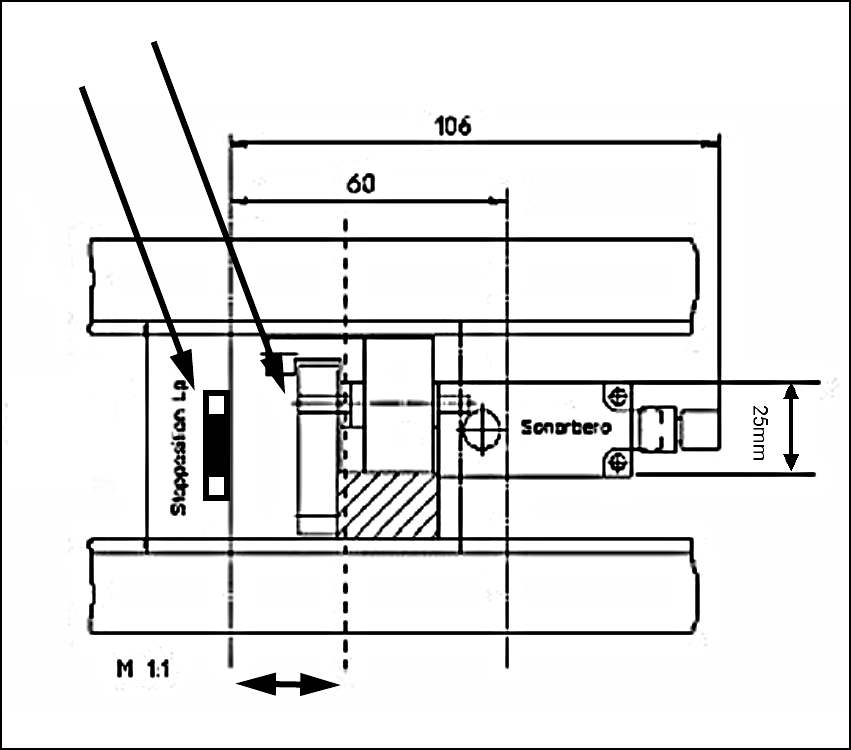
12.4 General
12.4.1 Stopper dimensions
Fig. 107 Stopper dimensions
Pivot unit
Stopper
Lifting table plate shortened by 27 mm
52 mm
Assembly Instructions PCB Stopper Single Conveyor SIPLACE S-27HM / HS-60 / D4 / D3 / HF- / X-Series
Edition 06/2007
133
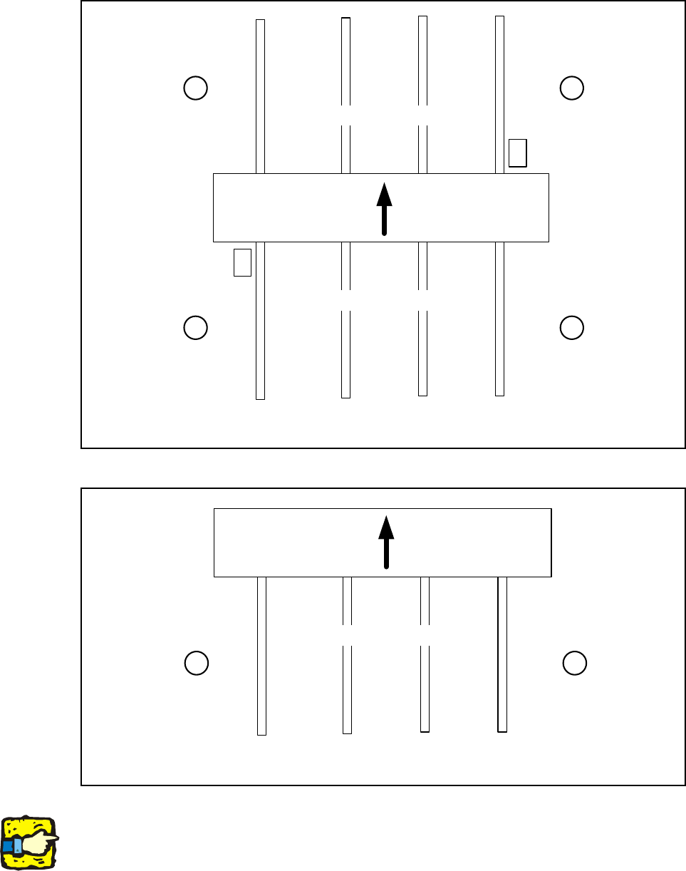
12.4.2 Overview of conveyor sides, locations, calibration pockets
Fig. 108 Overview of conveyor sides (HF, HF3, HS 60, D4, D3, X-Series)
Fig. 109 Overview of conveyor sides (S-27)
Note:
The calibration pocket is located in the middle of conveyor track 1 on the S-27.
1
23
4
Location Location
Location Location
Placement area 2
Placement area 1
Conveyor sides
4321
Calibration
pocket
Calibration
pocket
Transport
direction
12
Location Location
Placement area
Conveyor sides
4321
Transport
direction