NR_Mechanischer_Stopper.pdf - 第178页
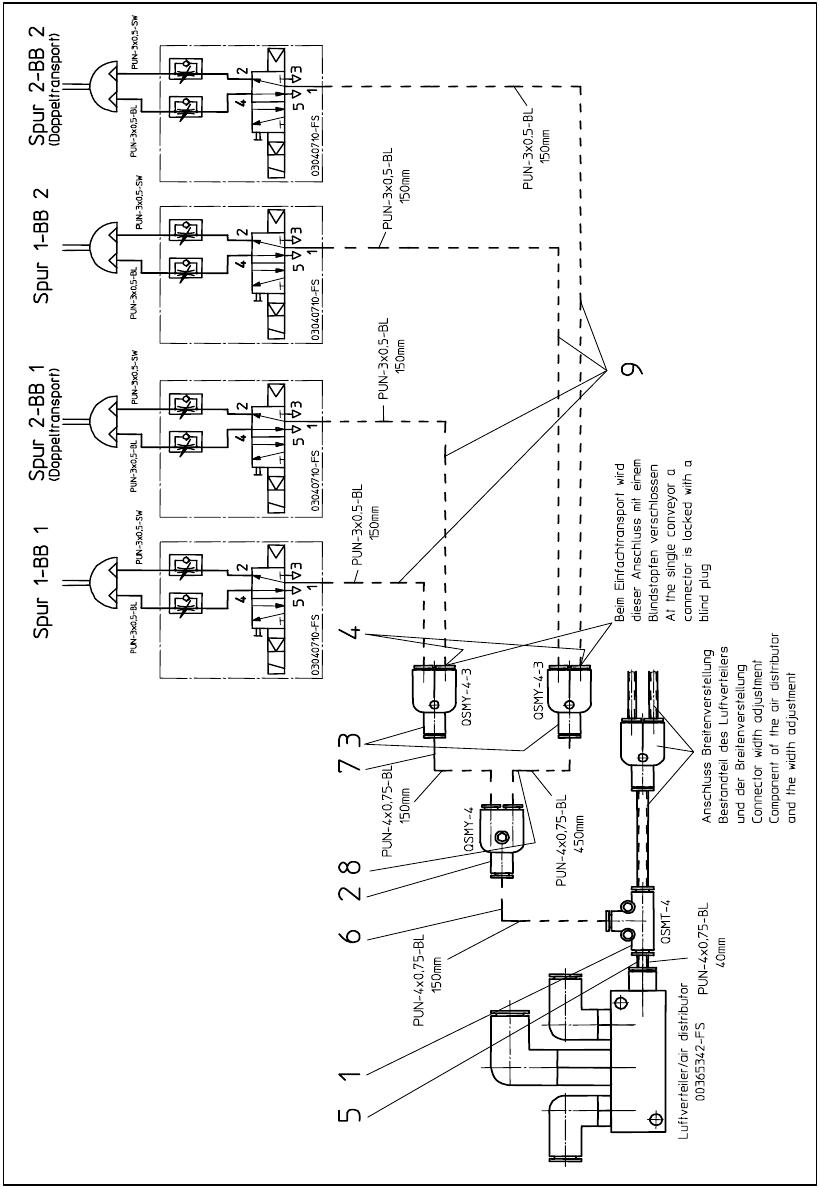
Assembly Instructions PCB Stopper Sin gle Conveyor SIPLACE S-27HM / HS-60 / D4 / D3 / HF- / X-Series Edition 06/2007 178 13.6 Pneumatics plan HS-60, D4 Fig. 153 Pneumatics plan HS-60, D4

Assembly Instructions PCB Stopper Single Conveyor SIPLACE S-27HM / HS-60 / D4 / D3 / HF- / X-Series
Edition 06/2007
177
O Fix all cables in position with self-adhesive cable clamps and cable ties.
O Fit the cable duct covers.
O Fit the metal cover over the cable duct (location 2).
O Fit the modified "Cover of conversion board for optional stopper" [03041584-xx].
O Fit the holder for the machine zero point and the nozzle changer, if removed earlier.
O Fit the plates of the lifting table for the optional stopper:
Caution: Crash hazard!
Check whether there are any objects left in the machine! Remove them.
O Switch on the placement machine at the main switch.
O Change to SITEST.
O Calibrate the reintegrated nozzel changer and the machine zero point on dual conveyor ma-
chines.
O Perform the settings according to:
"Setting the sonar proximity switches on the stopper" see section 16 on page - 221 13
"Software configuration and testing of the stopper" see section 18 on page - 227 13
13
Plate of lifting table Opt. Stopper HS DC PA1 SP1 [03041540-xx]
Plate of lifting table Opt. Stopper HS DC PA1 SP2 [03041541-xx]
Plate of lifting table Opt. Stopper HS DC PA2 SP1 [03041542-xx]
Plate of lifting table Opt. Stopper HS DC PA2 SP2 [03041543-xx]
Plate of lifting table Opt. Stopper HS SC PA1 [03036007-xx]
Plate of lifting table Opt. Stopper HS SC PA2 [03036934-xx]
Assembly Instructions PCB Stopper Single Conveyor SIPLACE S-27HM / HS-60 / D4 / D3 / HF- / X-Series
Edition 06/2007
178
13.6 Pneumatics plan HS-60, D4
Fig. 153 Pneumatics plan HS-60, D4

Assembly Instructions PCB Stopper Single Conveyor SIPLACE S-27HM / HS-60 / D4 / D3 / HF- / X-Series
Edition 06/2007
179
14 Retrofitting SIPLACE S-27HM
14.1 Preparatory work
Caution: Before the stopper is mounted in the machine, it should be adjusted with the guide strip
and the shims. Care should be taken to ensure that the stopper is not too loose or too tight. The
graduation of the shims is 0.1mm.
(See also Fig. 209, page - 232.) 14
14
O Changeover to the SITEST.
O Select "Conveyor" and "Conveyor width".
O Adjust the conveyor width to maximum.
O Undock the component trolley on both sides.
O Shut down the operating system and switch off the placement machine at the main switch.