NR_Mechanischer_Stopper.pdf - 第175页
Assembly Instructions PCB Stopper Single Conveyor SIPLACE S-27HM / HS-60 / D4 / D 3 / HF- / X-Series Edition 06/2007 175 Fig. 151 Cabling of optional PCB stopper HS-60/D4/D3/HF-Series/X-Series X 1 7 U m s e t z p l a t i…
Assembly Instructions PCB Stopper Single Conveyor SIPLACE S-27HM / HS-60 / D4 / D3 / HF- / X-Series
Edition 06/2007
174
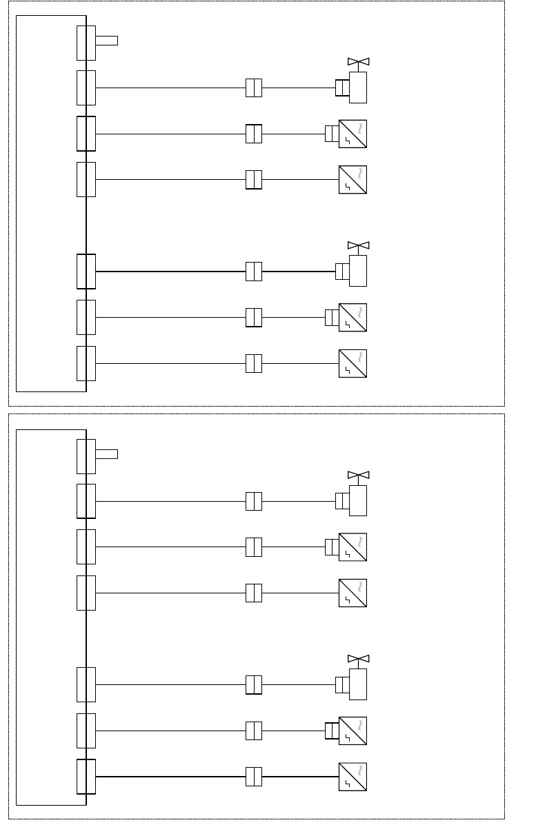
O Plug the connectors of the connecting lines onto the conversion board according to the wiring
plan.
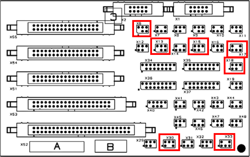
O Plug the coded plug onto location X6 on the conversion board for both conveyors.
Fig. 150 Terminal diagram for conversion board of PCB conveyor
Assembly Instructions PCB Stopper Single Conveyor SIPLACE S-27HM / HS-60 / D4 / D3 / HF- / X-Series
Edition 06/2007
175
Fig. 151 Cabling of optional PCB stopper HS-60/D4/D3/HF-Series/X-Series
X 1 7
U m s e t z p l a t i n e T r a n s p o r t , S p u r 1
C o n v e r s i o n b o a r d c o n v e y o r , l a n e 1
0 0 3 5 9 4 2 5 - x x ( k t )
X 1 7 k t
0 3 0 3 7 1 9 4 - x x
0 3 0 3 7 1 9 6 - x x
T r a n s p o r t s p u r 1 / C o n v e y o r l a n e 1 T r a n s p o r t s p u r 2 ( n u r b e i D o p p e l t r a n s p o r t ) / C o n v e y o r l a n e 2 ( d u a l c o n v e y o r o n l y )
0 3 0 3 7 2 0 0 - x x
X 1 3
X 1 3 k t
X 3 0
X 3 0 k t
X 1 8 k t
0 3 0 3 7 1 9 5 - x x
0 3 0 3 7 1 9 7 - x x
0 3 0 3 7 2 0 1 - x x
X 1 5 k tX 3 3 k t
B e s t ü c k b e r e i c h 1
P r o c e s s i n g a r e a 1
B e s t ü c k b e r e i c h 2
P r o c e s s i n g a r e a 2
X 1 8X 1 5X 3 3 X 1 7
U m s e t z p l a t i n e T r a n s p o r t , S p u r 2
C o n v e r s i o n b o a r d c o n v e y o r , l a n e 2
0 0 3 5 9 4 2 5 - x x ( k u )
X 1 7 k u
0 3 0 3 7 1 9 4 - x x
0 3 0 3 7 1 9 6 - x x
0 3 0 3 7 2 0 0 - x x
X 1 3
X 1 3 k u
X 3 0
X 3 0 k u
X 1 8 k u
0 3 0 3 7 1 9 5 - x x
0 3 0 3 7 1 9 7 - x x
0 3 0 3 7 2 0 1 - x x
X 1 5 k uX 3 3 k u
X 1 8X 1 5X 3 3
X 6
X 6 k t
X 6
X 6 k u
0 3 0 3 7 2 0 4 - x x
0 3 0 3 7 2 0 4 - x x
X a
X a
X b
X b
X a
X a
X b
X b
X a
X a
X b
X b
X a
X a
X b
X b
0 3 0 5 3 5 6 3 - x x
0 3 0 5 3 5 6 2 - x x
0 3 0 5 3 5 6 3 - x x
0 3 0 5 3 5 6 2 - x x
0 3 0 5 3 5 6 3 - x x
0 3 0 5 3 5 6 2 - x x
0 3 0 5 3 5 6 3 - x x
0 3 0 5 3 5 6 2 - x x
X c
X c X c X c
X d
X d
X d
X d
0 3 0 5 6 1 5 7 - x x
0 3 0 5 6 1 5 7 - x x
X d
X d
0 3 0 5 6 1 5 7 - x x
X d
X d
0 3 0 5 6 1 5 7 - x x
B e s t ü c k b e r e i c h 1
P r o c e s s i n g a r e a 1
B e s t ü c k b e r e i c h 2
P r o c e s s i n g a r e a 2
S o n a r b e r o
S o n a r s e n s o r
0 3 0 3 2 8 7 3 - x x
S e n s o r u n t e r e P o s i t i o n
S e n s o r l o w e r p o s i t i o n
V e n t i l
V a l v e
S o n a r b e r o
S o n a
r s e n s o r
0 3 0 3 2 8 7 3 - x x
S e n s o r u n t e r e P o s i t i o n
S e n s o r l o w e r p o s i t i o n
V e n t i l
V a l v e
S o n a r b e r o
S o n a r s e n s o r
0 3 0 3 2
8 7 3 - x x
S e n s o r u n t e r e P o s i t i o n
S e n s o r l o w e r p o s i t i o n
V e n t i l
V a l v e
S o n a r b e r o
S o n a r s e n s o r
0 3 0 3 2 8 7 3 - x x
S e n s o r
u n t e r e P o s i t i o n
S e n s o r l o w e r p o s i t i o n
V e n t i l
V a l v e
C o d i e r b r ü c k e " S t o p p e r S p u r 1 e i n g e b a u t "
C o d i n g j u m p e r " S t o p p e r l a n e 1 i n s t a l l e d "
C o d i e r b r ü c k e " S t o p p e r
S p u r 1 e i n g e b a u t "
C o d i n g j u m p e r " S t o p p e r l a n e 1 i n s t a l l e d "
Assembly Instructions PCB Stopper Single Conveyor SIPLACE S-27HM / HS-60 / D4 / D3 / HF- / X-Series
Edition 06/2007
176
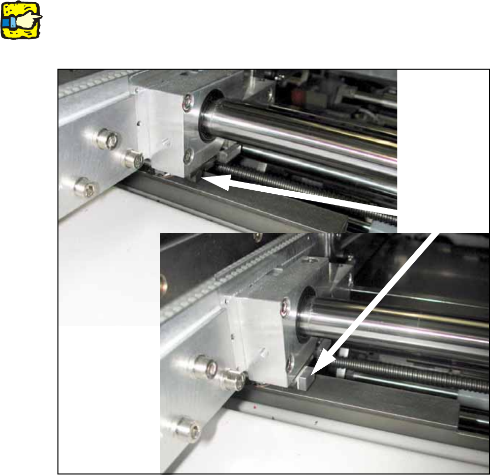
13.5 Concluding work
O Clean the adhesive surfaces for the distance pieces with a lint-free cloth moistened with ethyl
alcohol.
O Stick the distance pieces [03040724-xx] onto the limit switch actuator on the conveyor side with
the available adhesive tape. In placement area 1 the limit switch is located on conveyor sides
2 and 4 at the junction to the input/output.
13
13
13
This distance piece prevents the conveyor sides from coming within 52 mm of each other and so
prevents the PCB conveyor and the stoppers from being damaged. 13
13
Fig. 152 Position to stick distance piece
Stick here