NR_Mechanischer_Stopper.pdf - 第169页
Assembly Instructions PCB Stopper Single Conveyor SIPLACE S-27HM / HS-60 / D4 / D 3 / HF- / X-Series Edition 06/2007 169 13.4 Cable and hose laying HS-60, D4 13.4.1 Complete overview Fig. 146 Overview of pneumatic cablin…
Assembly Instructions PCB Stopper Single Conveyor SIPLACE S-27HM / HS-60 / D4 / D3 / HF- / X-Series
Edition 06/2007
168
O Affix the guide strip to the holders with two cylinder head bolts with hexagon socket head
M5 x 20-DIN 912 (see Fig. 145).
Fig. 145 Attach guide strip
The distance block stuck on the floor of the mounting tub must be positioned so that the trailing
cables run parallel to the guide strip of the stopper. 13
Screws
Assembly Instructions PCB Stopper Single Conveyor SIPLACE S-27HM / HS-60 / D4 / D3 / HF- / X-Series
Edition 06/2007
169
13.4 Cable and hose laying HS-60, D4
13.4.1 Complete overview
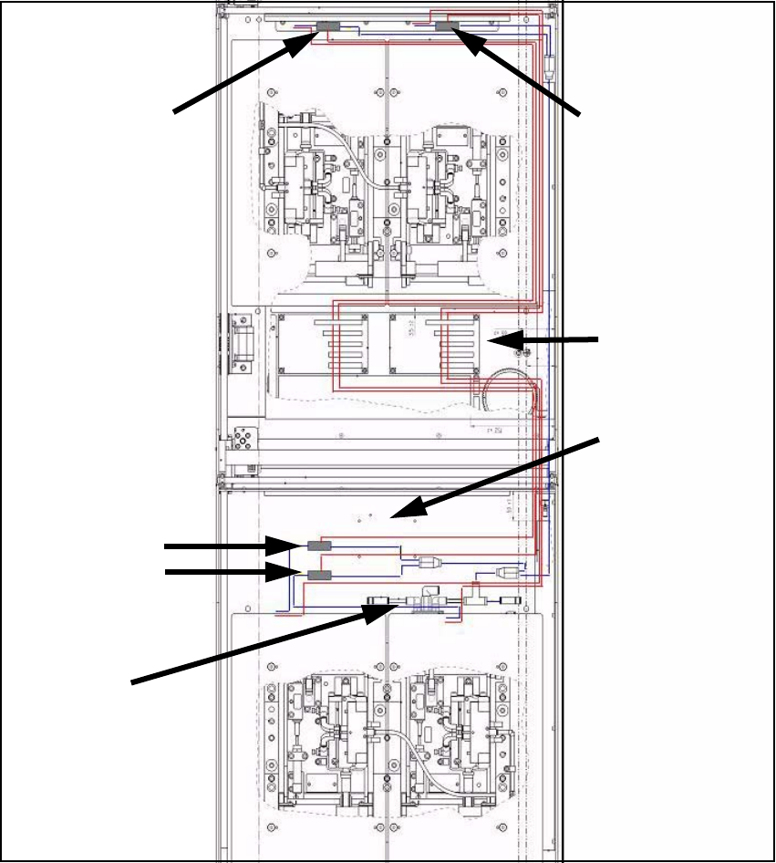
Fig. 146 Overview of pneumatic cabling (HS-60, D4)
Red lines: Power and data lines 13
Blue lines: Pneumatic power supply 13
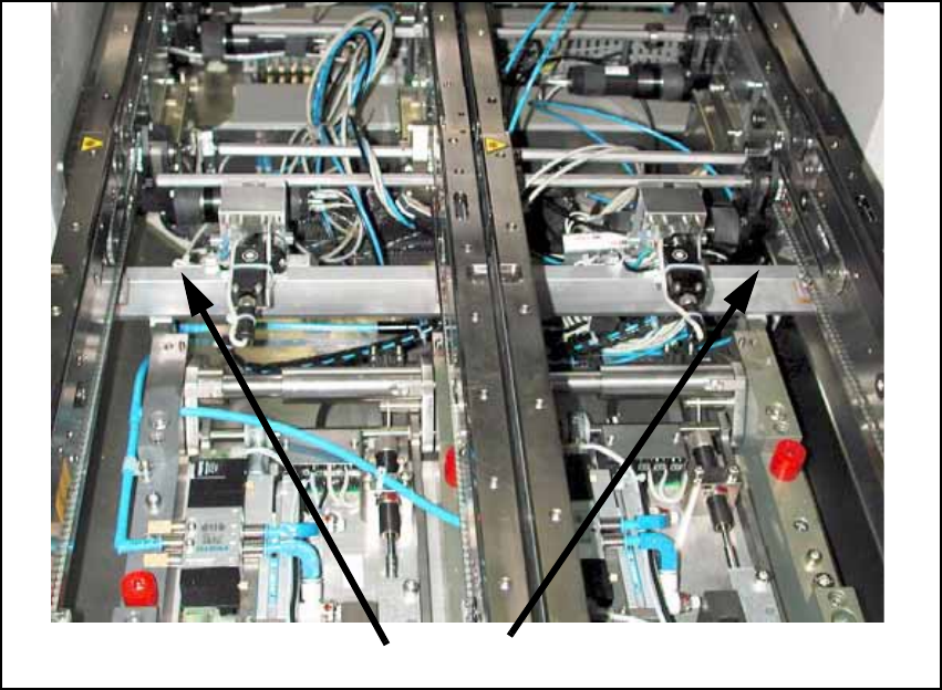
Position of sole-
noid valves PA2
Position of sole-
noid valves PA1
Conveyor
conversion
board
Area of activity of
conveyor side trail-
ing cables
(allow space!)
Pneumatic
feed line
Position of sole-
noid valves PA2
Assembly Instructions PCB Stopper Single Conveyor SIPLACE S-27HM / HS-60 / D4 / D3 / HF- / X-Series
Edition 06/2007
170
13.4.2 Cable and hose laying PA1
O Label the cables and pneumatic lines of the two stoppers to prevent any mix-ups.
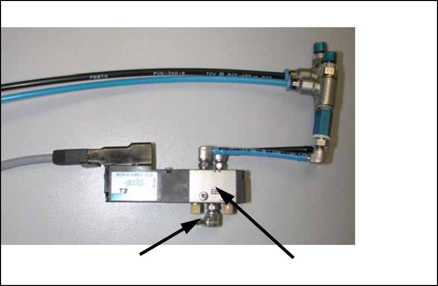
O Connect both air pressure supply hoses (PUN 3) with both magnetic valves.
O Route the supply air hose of the valve for PA2 with the cables of the stopper of PA1 into PA2 .
O Bundle the cables and hoses with cable ties and fix the cables in position with self-adhesive
cable clamps.
O Plug the connectors of the connecting lines onto the conversion board according to the circuit
diagram (see Fig. 151, page - 175).
air pressure supply
magnetic valve