NR_Mechanischer_Stopper.pdf - 第207页
Assembly Instructions PCB Stopper Single Conveyor SIPLACE S-27HM / HS-60 / D4 / D 3 / HF- / X-Series Edition 06/2007 207 15.3 Inst allation at placement area 2 Caution: Before the stopper is mou nted in the mach ine, it …
Assembly Instructions PCB Stopper Single Conveyor SIPLACE S-27HM / HS-60 / D4 / D3 / HF- / X-Series
Edition 06/2007
206
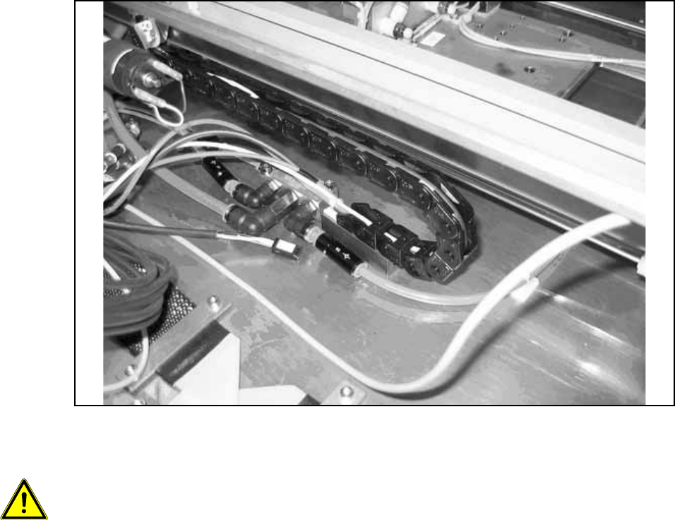
O For a single conveyor, stick the distance block onto the position of conveyor track 1. The stop-
per must be able to slide over the entire conveyor width. The distance block stuck on the floor
of the mounting tub must be positioned so that the trailing cables run parallel to the guide strip
of the stopper. If other cables prevent this, they must be repositioned.
Fig. 186
15
Caution, crash hazard:
– It is essential to ensure that the stopper and the trailing cables do not collide with the width
adjustment or its conveyor belt.
– The stoppers must be able to slide over the entire conveyor width.
– The trailing cable of conveyor track 1 must run exactly on the trailing cable of the stopper in
conveyor track 2 and must not tilt to the side.
– The distance between the two distance blocks should be approx. 100 mm.
– The laying of cables and tubing are described in a later section for functional reasons.
Assembly Instructions PCB Stopper Single Conveyor SIPLACE S-27HM / HS-60 / D4 / D3 / HF- / X-Series
Edition 06/2007
207
15.3 Installation at placement area 2
Caution: Before the stopper is mounted in the machine, it should be adjusted with the guide strip
and the shims. Care should be taken to ensure that the stopper is not too loose or too tight. The
graduation of the shims is 0.1mm.
(See also Fig. 209, page - 232.)
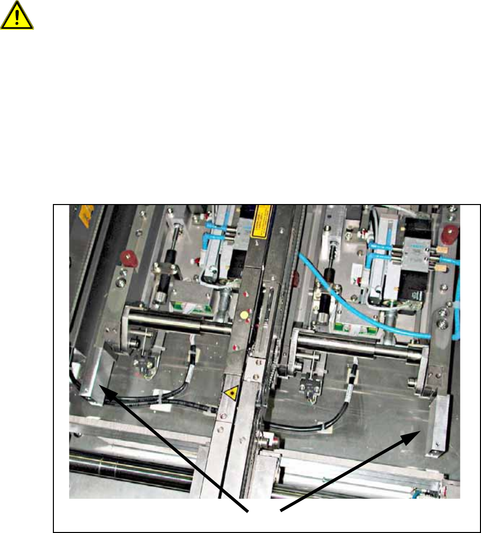
15.3.1 Installation of the holders
O Install the "Guide strip holders PA2 HF" [03032320-xx] for the guide strip of the PCB stopper.
The holders are installed so that they are flush at the top with the lateral frames of the lifting
table. To prevent the holder from twisting, the lateral shoulder of the holder must lie against the
outside of the frames.
Fasten each of the holders with a cylinder head bolt with hexagon socket head
M4 x 40-DIN 912.
Fig. 187 Holders
Holders
Assembly Instructions PCB Stopper Single Conveyor SIPLACE S-27HM / HS-60 / D4 / D3 / HF- / X-Series
Edition 06/2007
208
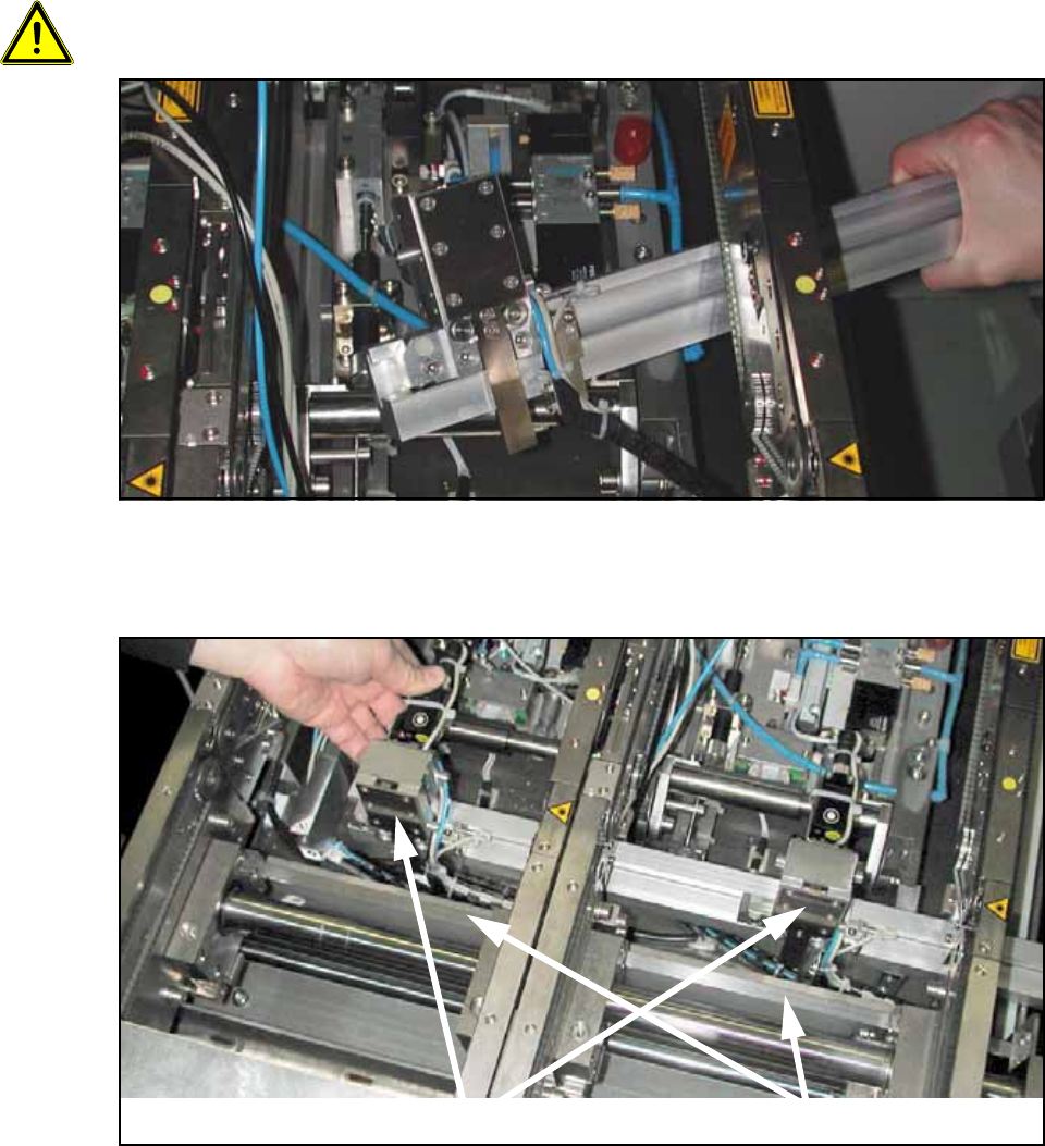
15.3.2 Installation of the stopper
O Clean the conveyor tub in the area of the guide strip with a lint-free cloth moistened with ethyl
alcohol.
O Push the guide strip into the conveyor from outside. Push the stopper units carefully between
the two side sections into the guide slot of the guide strip.
Be careful not to damage the sliding guides when pushing them onto the guide rail.
Fig. 188 Guide strip
O Hold the guide strip in its final position. Test whether the trailing cable can move freely by push-
ing it to the end from the side.
Fig. 189
Stopper
Terminal strip of width adjust-