NR_Mechanischer_Stopper.pdf - 第134页
Assembly Instructions PCB Stopper Sin gle Conveyor SIPLACE S-27HM / HS-60 / D4 / D3 / HF- / X-Series Edition 06/2007 134 12.4.3 Overview of stopper Fig. 1 10 Overview of stopper 12.4.3.1 High and low dist ance blocks Not…
Assembly Instructions PCB Stopper Single Conveyor SIPLACE S-27HM / HS-60 / D4 / D3 / HF- / X-Series
Edition 06/2007
133
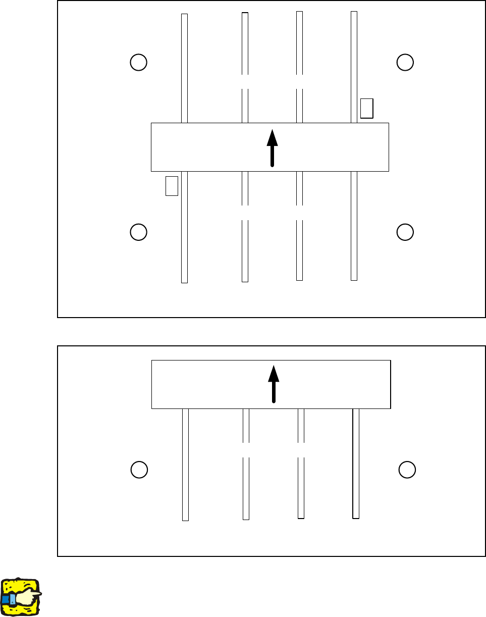
12.4.2 Overview of conveyor sides, locations, calibration pockets
Fig. 108 Overview of conveyor sides (HF, HF3, HS 60, D4, D3, X-Series)
Fig. 109 Overview of conveyor sides (S-27)
Note:
The calibration pocket is located in the middle of conveyor track 1 on the S-27.
1
23
4
Location Location
Location Location
Placement area 2
Placement area 1
Conveyor sides
4321
Calibration
pocket
Calibration
pocket
Transport
direction
12
Location Location
Placement area
Conveyor sides
4321
Transport
direction
Assembly Instructions PCB Stopper Single Conveyor SIPLACE S-27HM / HS-60 / D4 / D3 / HF- / X-Series
Edition 06/2007
134
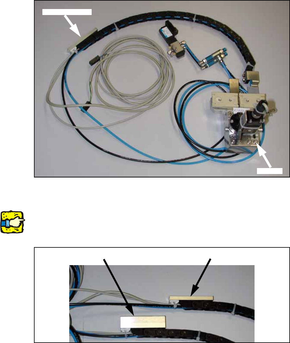
12.4.3 Overview of stopper
Fig. 110 Overview of stopper
12.4.3.1 High and low distance blocks
Note:
A distance block is screwed onto the loose end of the trailing cable. The height of this spacer var-
ies depending on the conveyor track and is stuck onto the floor of the mounting tub with adhesive
tape.
Fig. 111 High and low distance blocks
Distance block
Stopper
Low distance block
High distance block
Assembly Instructions PCB Stopper Single Conveyor SIPLACE S-27HM / HS-60 / D4 / D3 / HF- / X-Series
Edition 06/2007
135
The stoppers with high and low distance blocks are used as follows:
Article numbers:
– Distance block high: [03043305-xx]
– Distance block low: [03043306-xx]
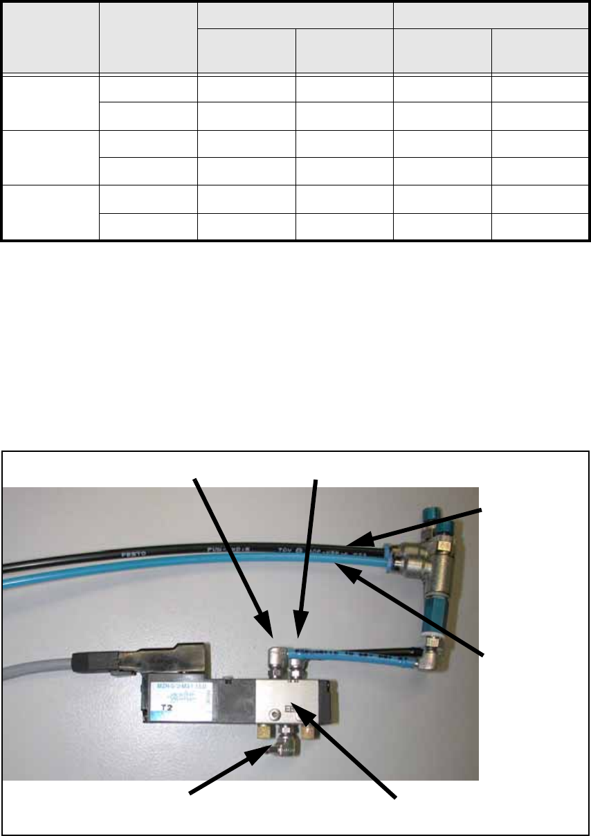
12.4.3.2 Description of solenoid valves and hoses:
Fig. 113 Solenoid valves and hoses
Machine Conveyor
type
Placement area 1 Placement area 2
Conveyor
track 1
Conveyor
track 2
Conveyor
track 1
Conveyor
track 2
HS-60 / D4
Single high --- low ---
Dual high low high low
S-27HM
Single low --- --- ---
Dual high low --- ---
HF- / X-
Series / D3
Single high --- low ---
Dual high low high low
Tab. 12. 112 Use of stoppers with high and low distance blocks
Connection 4 Connection 2
Black = Connec-
tion of rotating
cylinder
Insert stopper
with adjustable
throttle
Blue = Connec-
tion of rotating
cylinder
Withdraw stop-
per with adjust-
able throttle
Compressed air
supply
Solenoid valve