NR_Mechanischer_Stopper.pdf - 第176页
Assembly Instructions PCB Stopper Sin gle Conveyor SIPLACE S-27HM / HS-60 / D4 / D3 / HF- / X-Series Edition 06/2007 176 13.5 Concluding work O Clean the adhesive sur faces for the distan ce piec es with a lint-free clot…
Assembly Instructions PCB Stopper Single Conveyor SIPLACE S-27HM / HS-60 / D4 / D3 / HF- / X-Series
Edition 06/2007
175
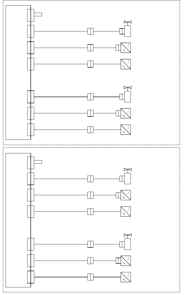
Fig. 151 Cabling of optional PCB stopper HS-60/D4/D3/HF-Series/X-Series
X 1 7
U m s e t z p l a t i n e T r a n s p o r t , S p u r 1
C o n v e r s i o n b o a r d c o n v e y o r , l a n e 1
0 0 3 5 9 4 2 5 - x x ( k t )
X 1 7 k t
0 3 0 3 7 1 9 4 - x x
0 3 0 3 7 1 9 6 - x x
T r a n s p o r t s p u r 1 / C o n v e y o r l a n e 1 T r a n s p o r t s p u r 2 ( n u r b e i D o p p e l t r a n s p o r t ) / C o n v e y o r l a n e 2 ( d u a l c o n v e y o r o n l y )
0 3 0 3 7 2 0 0 - x x
X 1 3
X 1 3 k t
X 3 0
X 3 0 k t
X 1 8 k t
0 3 0 3 7 1 9 5 - x x
0 3 0 3 7 1 9 7 - x x
0 3 0 3 7 2 0 1 - x x
X 1 5 k tX 3 3 k t
B e s t ü c k b e r e i c h 1
P r o c e s s i n g a r e a 1
B e s t ü c k b e r e i c h 2
P r o c e s s i n g a r e a 2
X 1 8X 1 5X 3 3 X 1 7
U m s e t z p l a t i n e T r a n s p o r t , S p u r 2
C o n v e r s i o n b o a r d c o n v e y o r , l a n e 2
0 0 3 5 9 4 2 5 - x x ( k u )
X 1 7 k u
0 3 0 3 7 1 9 4 - x x
0 3 0 3 7 1 9 6 - x x
0 3 0 3 7 2 0 0 - x x
X 1 3
X 1 3 k u
X 3 0
X 3 0 k u
X 1 8 k u
0 3 0 3 7 1 9 5 - x x
0 3 0 3 7 1 9 7 - x x
0 3 0 3 7 2 0 1 - x x
X 1 5 k uX 3 3 k u
X 1 8X 1 5X 3 3
X 6
X 6 k t
X 6
X 6 k u
0 3 0 3 7 2 0 4 - x x
0 3 0 3 7 2 0 4 - x x
X a
X a
X b
X b
X a
X a
X b
X b
X a
X a
X b
X b
X a
X a
X b
X b
0 3 0 5 3 5 6 3 - x x
0 3 0 5 3 5 6 2 - x x
0 3 0 5 3 5 6 3 - x x
0 3 0 5 3 5 6 2 - x x
0 3 0 5 3 5 6 3 - x x
0 3 0 5 3 5 6 2 - x x
0 3 0 5 3 5 6 3 - x x
0 3 0 5 3 5 6 2 - x x
X c
X c X c X c
X d
X d
X d
X d
0 3 0 5 6 1 5 7 - x x
0 3 0 5 6 1 5 7 - x x
X d
X d
0 3 0 5 6 1 5 7 - x x
X d
X d
0 3 0 5 6 1 5 7 - x x
B e s t ü c k b e r e i c h 1
P r o c e s s i n g a r e a 1
B e s t ü c k b e r e i c h 2
P r o c e s s i n g a r e a 2
S o n a r b e r o
S o n a r s e n s o r
0 3 0 3 2 8 7 3 - x x
S e n s o r u n t e r e P o s i t i o n
S e n s o r l o w e r p o s i t i o n
V e n t i l
V a l v e
S o n a r b e r o
S o n a
r s e n s o r
0 3 0 3 2 8 7 3 - x x
S e n s o r u n t e r e P o s i t i o n
S e n s o r l o w e r p o s i t i o n
V e n t i l
V a l v e
S o n a r b e r o
S o n a r s e n s o r
0 3 0 3 2
8 7 3 - x x
S e n s o r u n t e r e P o s i t i o n
S e n s o r l o w e r p o s i t i o n
V e n t i l
V a l v e
S o n a r b e r o
S o n a r s e n s o r
0 3 0 3 2 8 7 3 - x x
S e n s o r
u n t e r e P o s i t i o n
S e n s o r l o w e r p o s i t i o n
V e n t i l
V a l v e
C o d i e r b r ü c k e " S t o p p e r S p u r 1 e i n g e b a u t "
C o d i n g j u m p e r " S t o p p e r l a n e 1 i n s t a l l e d "
C o d i e r b r ü c k e " S t o p p e r
S p u r 1 e i n g e b a u t "
C o d i n g j u m p e r " S t o p p e r l a n e 1 i n s t a l l e d "
Assembly Instructions PCB Stopper Single Conveyor SIPLACE S-27HM / HS-60 / D4 / D3 / HF- / X-Series
Edition 06/2007
176
13.5 Concluding work
O Clean the adhesive surfaces for the distance pieces with a lint-free cloth moistened with ethyl
alcohol.
O Stick the distance pieces [03040724-xx] onto the limit switch actuator on the conveyor side with
the available adhesive tape. In placement area 1 the limit switch is located on conveyor sides
2 and 4 at the junction to the input/output.
13
13
13
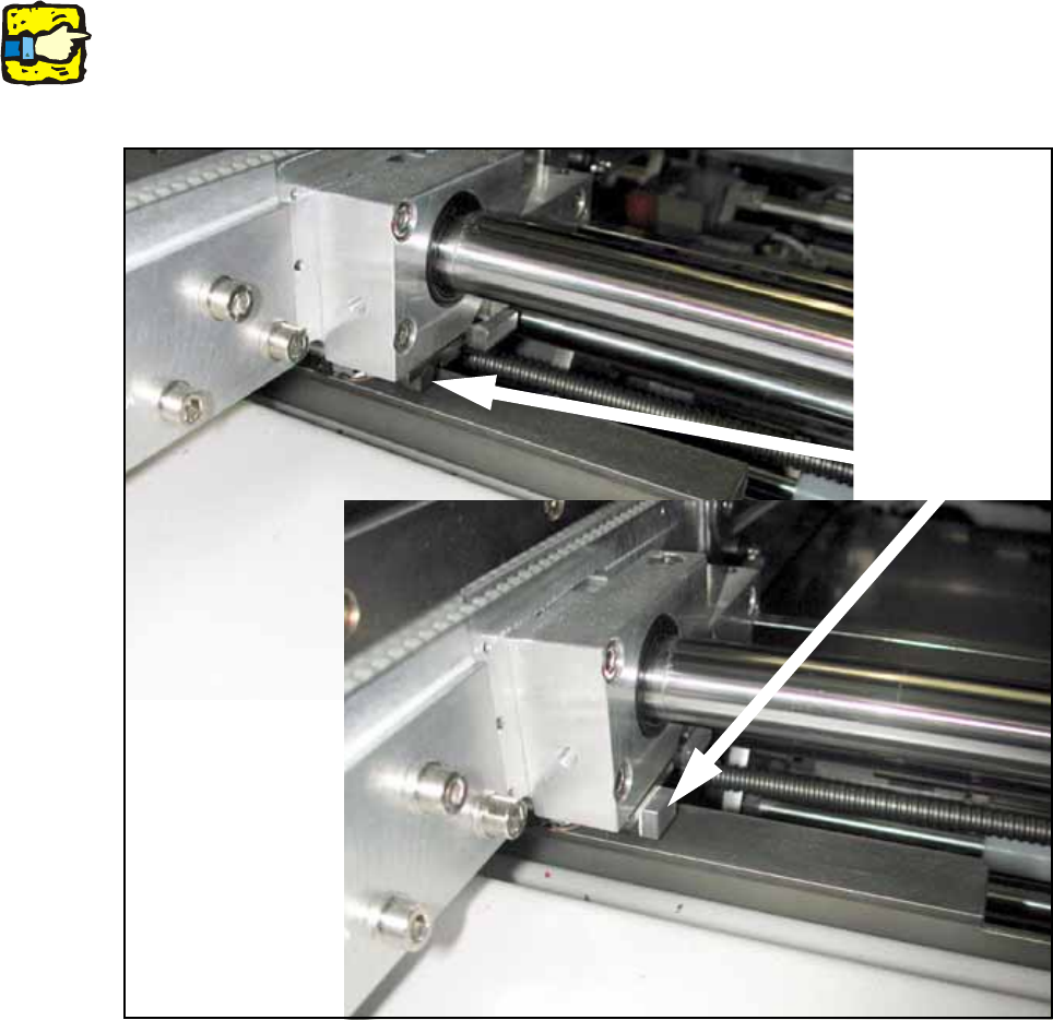
This distance piece prevents the conveyor sides from coming within 52 mm of each other and so
prevents the PCB conveyor and the stoppers from being damaged. 13
13
Fig. 152 Position to stick distance piece
Stick here

Assembly Instructions PCB Stopper Single Conveyor SIPLACE S-27HM / HS-60 / D4 / D3 / HF- / X-Series
Edition 06/2007
177
O Fix all cables in position with self-adhesive cable clamps and cable ties.
O Fit the cable duct covers.
O Fit the metal cover over the cable duct (location 2).
O Fit the modified "Cover of conversion board for optional stopper" [03041584-xx].
O Fit the holder for the machine zero point and the nozzle changer, if removed earlier.
O Fit the plates of the lifting table for the optional stopper:
Caution: Crash hazard!
Check whether there are any objects left in the machine! Remove them.
O Switch on the placement machine at the main switch.
O Change to SITEST.
O Calibrate the reintegrated nozzel changer and the machine zero point on dual conveyor ma-
chines.
O Perform the settings according to:
"Setting the sonar proximity switches on the stopper" see section 16 on page - 221 13
"Software configuration and testing of the stopper" see section 18 on page - 227 13
13
Plate of lifting table Opt. Stopper HS DC PA1 SP1 [03041540-xx]
Plate of lifting table Opt. Stopper HS DC PA1 SP2 [03041541-xx]
Plate of lifting table Opt. Stopper HS DC PA2 SP1 [03041542-xx]
Plate of lifting table Opt. Stopper HS DC PA2 SP2 [03041543-xx]
Plate of lifting table Opt. Stopper HS SC PA1 [03036007-xx]
Plate of lifting table Opt. Stopper HS SC PA2 [03036934-xx]