NR_Mechanischer_Stopper.pdf - 第192页
Assembly Instructions PCB Stopper Sin gle Conveyor SIPLACE S-27HM / HS-60 / D4 / D3 / HF- / X-Series Edition 06/2007 192 Fig. 171 Cabling of optional PCB stopper (S27 ) O Det ach the blind plug from the pneumatic distr i…
Assembly Instructions PCB Stopper Single Conveyor SIPLACE S-27HM / HS-60 / D4 / D3 / HF- / X-Series
Edition 06/2007
191
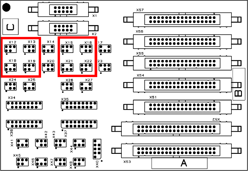
O Plug all the connectors (1 sensor, 1 sonar proximity switch, 1 solenoid valve and 1 bridge for
each conveyor track) onto the conversion board.
Fig. 170 Terminal plan for conversion board
Assembly Instructions PCB Stopper Single Conveyor SIPLACE S-27HM / HS-60 / D4 / D3 / HF- / X-Series
Edition 06/2007
192
Fig. 171 Cabling of optional PCB stopper (S27)
O Detach the blind plug from the pneumatic distributor.
Fig. 172 Supply hose
X 1 9 / 2 2
U m s e t z p l a t i n e T r a n s p o r t
C o n v e r s i o n b o a r d c o n v e y o r
0 0 3 5 9 4 2 6 - x x ( k t )
X 1 9 k t
S o n a r b e r o
S o n a r s e n s o r
0 3 0 3 2 8 7 3 - x x
S e n s o r u n t e r e P o s i t i o n
S e n s o r l o w e r p o s i t i o n
V e n t i l
V a l v e
0 3 0 3 7 8 6 1 - x x
0 3 0 3 7 8 6 0 - x x
T r a n s p o r t s p u r 1 T r a n s p o r t s p u r 2 ( n u r b e i D o p p e l t r a n s p o r t )
0 3 0 3 7 8 5 9 - x x
X 1 3 / 1 6
X 1 3 k t
X 1 8 / 2 1
X 1 8 k t
X 2 2 k t
0 3 0 3 7 8 6 1 - x x
0 3 0 3 7 8 6 0 - x x
0 3 0 3 7 8 5 9 - x x
X 1 6 k tX 2 1 k t
X 1 9 / 2 2X 1 3 / 1 6X 1 8 / 2 1
X 1 2 / 1 5
X 1 5 k t
C o d i e r b r ü c k e " S t o p p e r S p u r 1 e i n g e b a u t "
C o d i n g j u m p e r " S t o p p e r l a n e 1 i n s t a l l e d "
X 1 2 / 1 5
X 1 2 k t
0 3 0 3 7 8 6 2 - x x
X a
X a
X b
X b
0 3 0 5 3 5 6 3 - x x
0 3 0 5 3 5 6 2 - x x
X a
X a
X b
X b
0 3 0 5 3 5 6 3 - x x
0 3 0 5 3 5 6 2 - x x
X c X c
X d
X d
0 3 0 5 6 1 5 7 - x x
X d
X d
0 3 0 5 6 1 5 7 - x x
C o n v e y o r l a n e 1 C o n v e y o r l a n e 2 ( d u a l c o n v e y o r o n l y )
V e n t i l
V a l v e
S o n a r b e r o
S o n a r s e n s o r
0 3 0 3 2 8 7 3 - x x
S e n s o r u n t e r e P o s i t i o n
S e n s o r l o w e r p o s i t i o n
C o d i e r b r ü c k e " S t o p p e r S p u r 2 e i n g e b a u t "
C o d i n g j u m p e r " S t o p p e r l a n e 2 i n s t a l l e d "
0 3 0 3 7 8 6 2 - x x
Blind plug
Assembly Instructions PCB Stopper Single Conveyor SIPLACE S-27HM / HS-60 / D4 / D3 / HF- / X-Series
Edition 06/2007
193
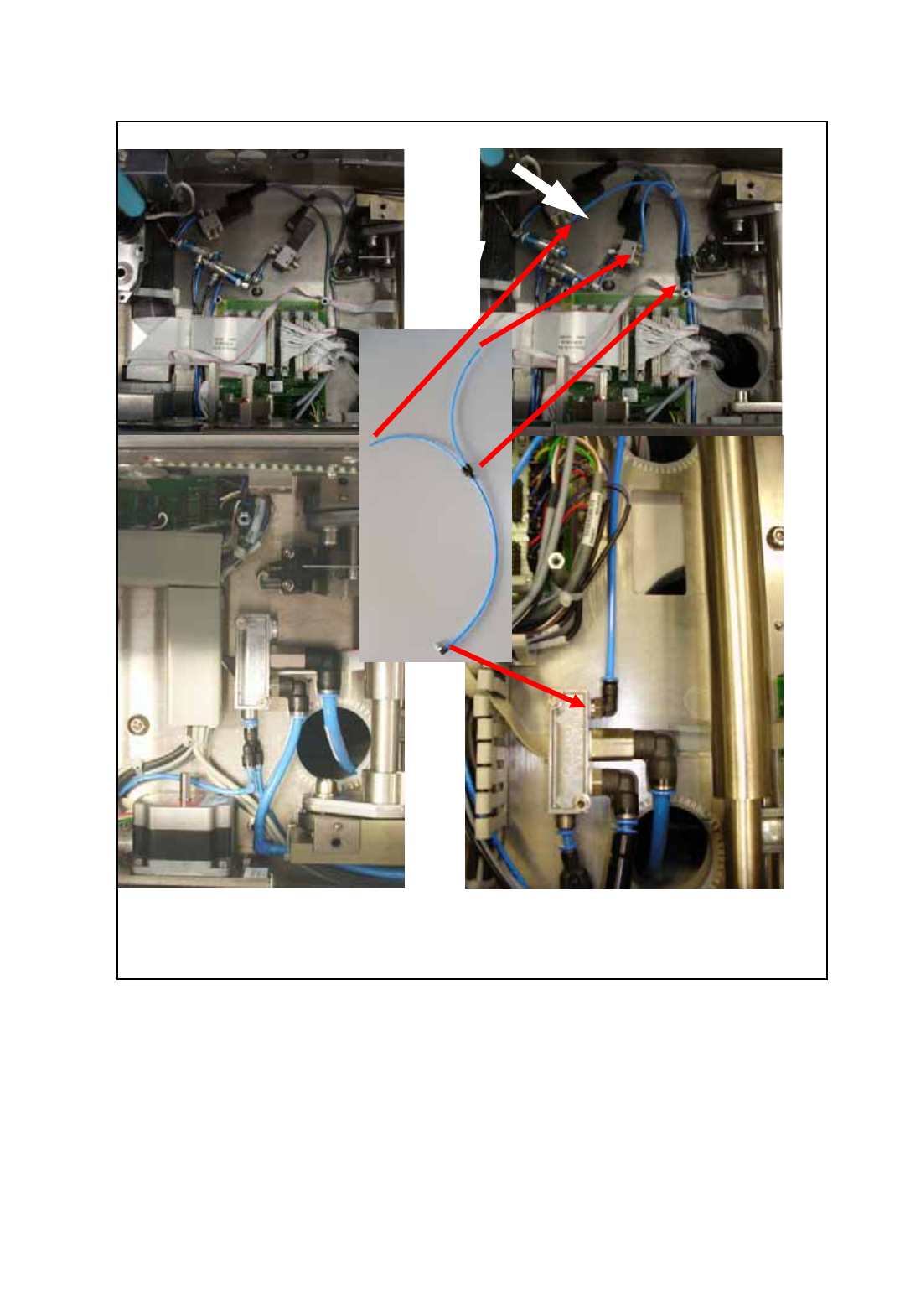
before installation after installation
O Connect the feed line for the pneumatic valves to the conveyor pneumatic distributor as shown
in the following figure.
Fig. 173 Installation of the feed line for the pneumatic valves