NR_Mechanischer_Stopper.pdf - 第153页
Assembly Instructions PCB Stopper Single Conveyor SIPLACE S-27HM / HS-60 / D4 / D 3 / HF- / X-Series Edition 06/2007 153 O Inst all the holders for the guide rail ([0303692 8-xx] and [03032179-xx]), (narrow holders for P…
Assembly Instructions PCB Stopper Single Conveyor SIPLACE S-27HM / HS-60 / D4 / D3 / HF- / X-Series
Edition 06/2007
152
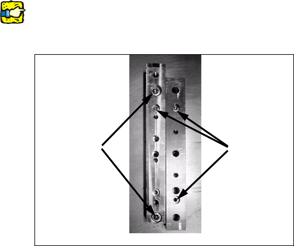
O Remove the distance pieces and replace them with the optional distance pieces [03040964-
xx] (single conveyor 2 pcs. / dual conveyor 3 pcs.).
To do this, use one screw from the original distance piece to pre-position each new piece and
two M8 x 50 - DIN 6912 to fasten it.
For the single conveyor 2 distance pieces must be exchanged here, and for the dual conveyor
3 distance pieces.
13
13
The new distance pieces must be parallel when installed in the conveyor tub so that the alignment
pins of the lifting table can be easily sunk into the new distance pieces.
If they are not already preassembled on the distance piece, use the supplied alignment pins for
this. 13
13
Fig. 128 Distance pieces
M6x50 mm
M8x50 mm
Optional distance piece
[03040964-xx]
New (left) and old (right) distance piece
Assembly Instructions PCB Stopper Single Conveyor SIPLACE S-27HM / HS-60 / D4 / D3 / HF- / X-Series
Edition 06/2007
153
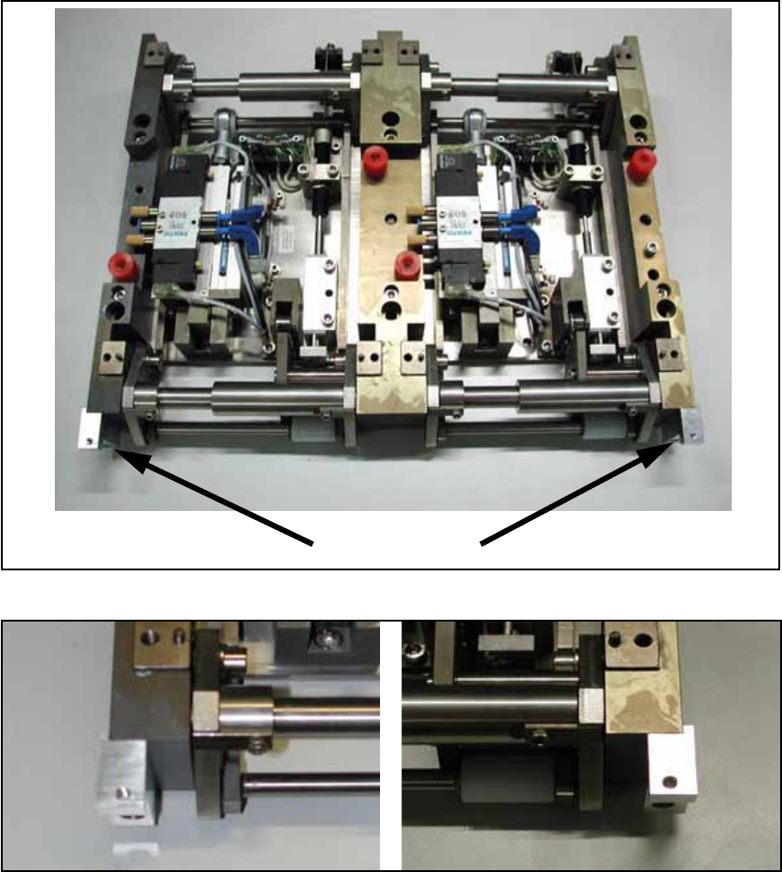
O Install the holders for the guide rail ([03036928-xx] and [03032179-xx]), (narrow holders for
PA1, wide ones for PA2), with one cylinder head bolt (each) with hexagon socket head
M4 x 16-DIN 912 on the lifting table PA2. The holders are installed so that they are flush at the
top with the lateral frames of the lifting table.To prevent the holder from twisting, the lateral
shoulder of the holder must lie against the outside of the frames.
Fig. 129 Guide rail holders
Fig. 130
Guide rail holders at left and right
Guide rail holders
Assembly Instructions PCB Stopper Single Conveyor SIPLACE S-27HM / HS-60 / D4 / D3 / HF- / X-Series
Edition 06/2007
154
O Clean the conveyor tub in the area of the conveyor width adjustment with a lint-free cloth moist-
ened with ethyl alcohol.
The tub should be free of grease as the trailing cables are to be fastened here with double-
sided adhesive tape.
13
13
When you place the lifting table back in the conveyor, be careful not to damage either the con-
veyor, the lifting table (forked light barrier) or cables/hoses. 13
13
O Insert the lifting table. Place it on the distance pieces.
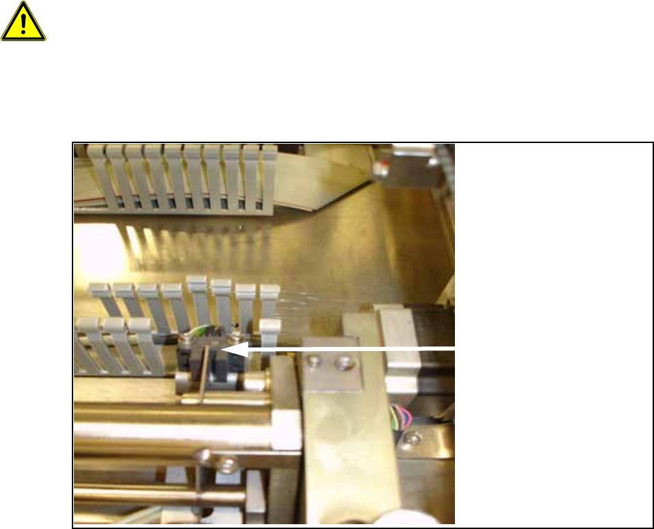
O Remove 3 to 4 segments of the cable duct in the area of the lifting table's forked light barriers.
O Detach the cable clamp for the control cable of the lifting table.
Remove 3 to 4
segments for the forked
light barriers.