NR_Mechanischer_Stopper.pdf - 第172页
Assembly Instructions PCB Stopper Sin gle Conveyor SIPLACE S-27HM / HS-60 / D4 / D3 / HF- / X-Series Edition 06/2007 172 13.4.3 Cable and hose laying P A2 O Route the cables in the cable du ct to th e conversion boards o…
Assembly Instructions PCB Stopper Single Conveyor SIPLACE S-27HM / HS-60 / D4 / D3 / HF- / X-Series
Edition 06/2007
171
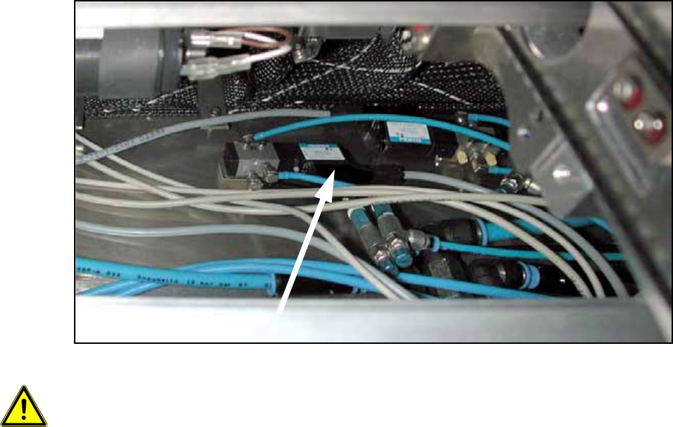
O Stick the valves onto the mounting tub with double-sided adhesive tape as shown in the fig-
ures.
Fig. 147 Valves
13
Make sure that the trailing cables of the conveyor sides are not impeded in their movement. 13
13
Valves
Assembly Instructions PCB Stopper Single Conveyor SIPLACE S-27HM / HS-60 / D4 / D3 / HF- / X-Series
Edition 06/2007
172
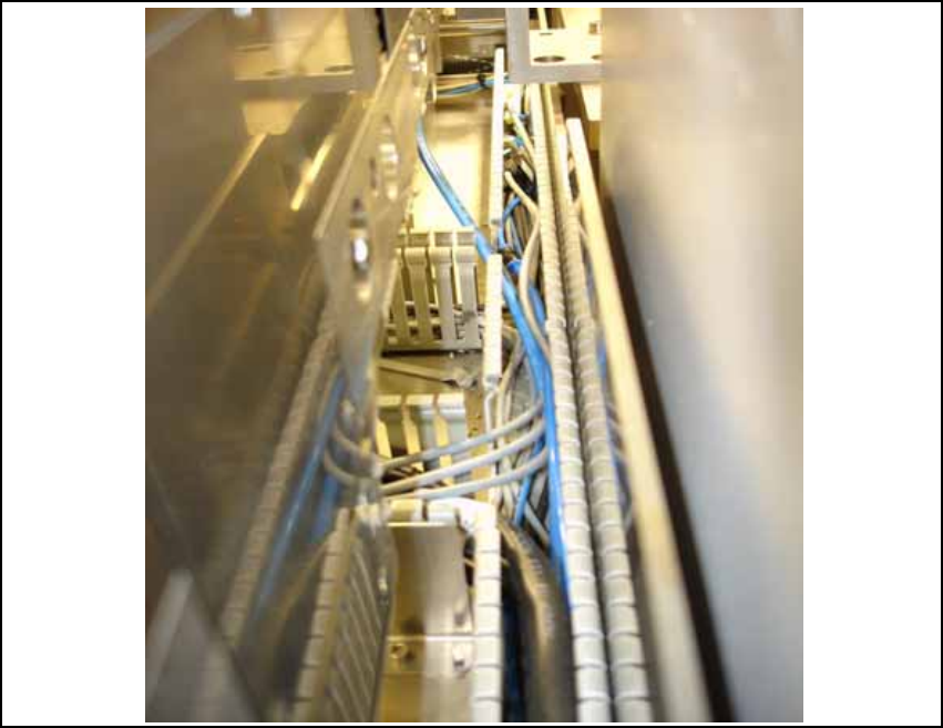
13.4.3 Cable and hose laying PA2
O Route the cables in the cable duct to the conversion boards of the PCB conveyor.
Fig. 148
13
Assembly Instructions PCB Stopper Single Conveyor SIPLACE S-27HM / HS-60 / D4 / D3 / HF- / X-Series
Edition 06/2007
173
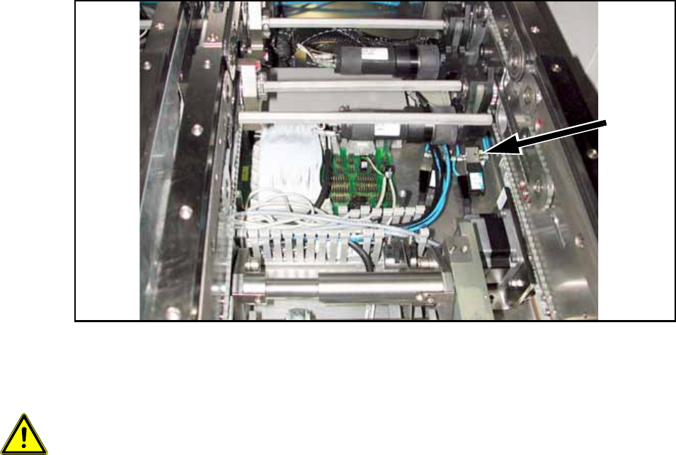
O Stow the cables in the wide cable duct next to the conversion boards.
13
13
Fig. 149
O Connect both air pressure supply hoses (PUN 3) with both magnetic valves.
O Stick the valves onto the mounting tub with double-sided adhesive tape as shown in the figure.
13
13
Make sure that no cables, hoses or valves touch the belt of the width adjustment. 13
13
13
Solenoid
valve