NR_Mechanischer_Stopper.pdf - 第221页
Retrofit Instructions PCB Stopper Single Conveyor SIPLACE S-27HM / HS-60 / D4 / D 3 / HF- / X-Series Issue 01/2007 221 16 Setting the sonar proximity switches on the stopper Fig. 200 LED SET button Plug-in connectio n of…
Assembly Instructions PCB Stopper Single Conveyor SIPLACE S-27HM / HS-60 / D4 / D3 / HF- / X-Series
Edition 06/2007
220
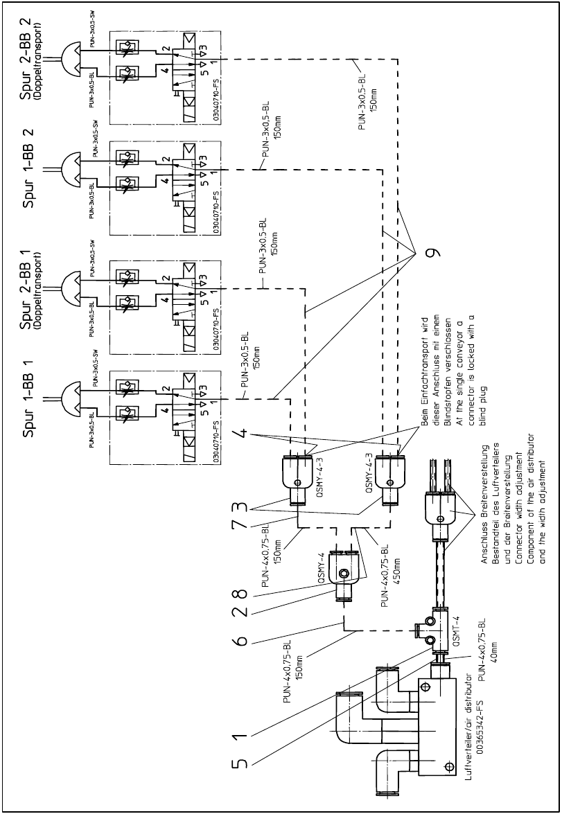
15.5 Pneumatics plan HF-, X-Series, D3
Fig. 199 Pneumatics plan HF-, X-Series, D3
Retrofit Instructions PCB Stopper Single Conveyor SIPLACE S-27HM / HS-60 / D4 / D3 / HF- / X-Series
Issue 01/2007
221
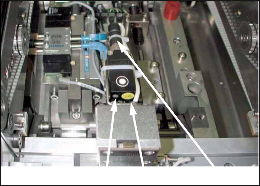
16 Setting the sonar proximity switches
on the stopper
Fig. 200
LED
SET button
Plug-in connection of sensor
Retrofit Instructions PCB Stopper Single Conveyor SIPLACE S-27HM / HS-60 / D4 / D3 / HF- / X-Series
Issue 01/2007
222
O Press the "Set" button on the sonar sensor until the LED to the left of the button starts to flash.
If the sensor does not react, briefly disconnect the plug at the back of the sensor.
Note:
The sonar proximity switch can be calibrated within the first 5 minutes after it has been switched
on. 16
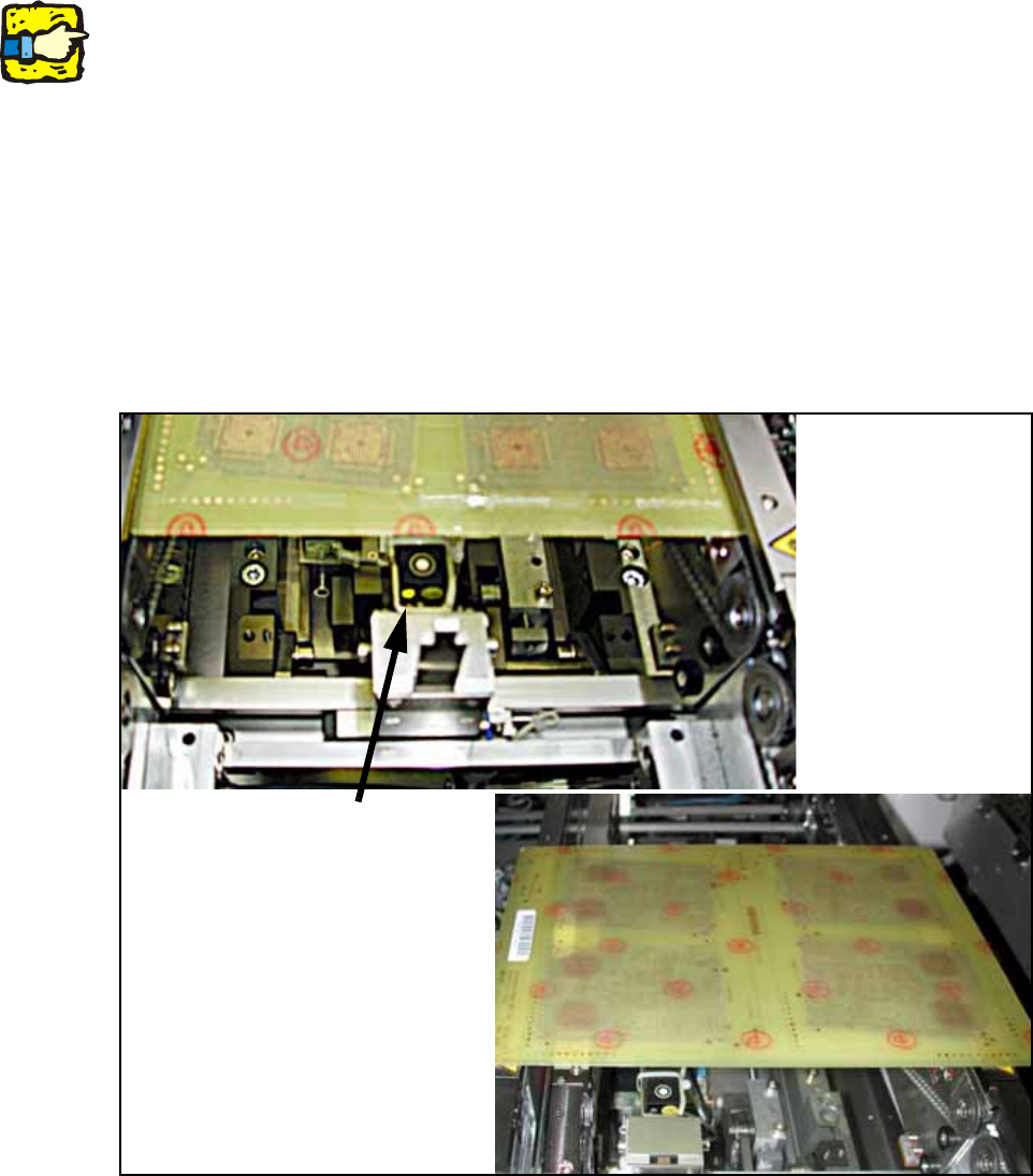
O Lay the PC board on the conveyor belt, push it over the stopper and press it against the clamp-
ing edge from below or lay the adjusting gauge for the sonar proximity switch on the clamping
edge (cutout facing downward, [03048764-xx]).
O Press the "Set" button again. The sensor adjusts itself to the PCB height.
The LED lights up.
O Remove the PCB/adjusting gauge and lay a PCB over the sensor onto the clamping edge.
The sensor should not detect the PC board. This setting must be checked for the entire con-
veyor width. The LED must be off, otherwise repeat the process.
Fig. 201 Sonar sensor
Sonar sensor