NR_Mechanischer_Stopper.pdf - 第218页
Assembly Instructions PCB Stopper Sin gle Conveyor SIPLACE S-27HM / HS-60 / D4 / D3 / HF- / X-Series Edition 06/2007 218 15.4 Concluding work O Clean the adhesive sur faces for the distan ce piec es with a lint-free clot…

Assembly Instructions PCB Stopper Single Conveyor SIPLACE S-27HM / HS-60 / D4 / D3 / HF- / X-Series
Edition 06/2007
217
15.3.3.3 Pneumatic tubing
Note:
Lay all the hoses so that there are no kinks.
Placement area 1 15
O Take the 2-way distributor with the short feed line and plug it onto the free connection on the
solenoid valve.
Note:
Shorten the hoses if necessary.
O If you have a single conveyor machine, remove the 2nd hose and replace it with a blind plug.
O Repeat the process for the 2nd solenoid valve.
O If necessary, fix the hoses in position with self-adhesive cable clamps and cable ties.
Placement area 2 15
O Take the 2-way distributor that you previously pushed toward the conversion board from PA1,
and lay it in the cable ducts to the solenoid valves in placement area 2.
O Plug the hose coming from the 2-way distributor onto the free connection on the solenoid valve.
Note:
Shorten the hoses if necessary.
O If you have a single conveyor machine, remove the 2nd hose and replace it with a blind plug.
O Repeat the process for the 2nd solenoid valve.
O If necessary, fix the hoses in position with self-adhesive cable clamps and cable ties.
Assembly Instructions PCB Stopper Single Conveyor SIPLACE S-27HM / HS-60 / D4 / D3 / HF- / X-Series
Edition 06/2007
218
15.4 Concluding work
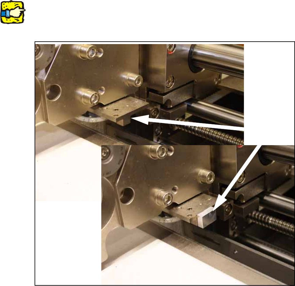
O Clean the adhesive surfaces for the distance pieces with a lint-free cloth moistened with ethyl
alcohol.
O Stick the distance pieces [03040724-xx] onto the limit switch actuator on the conveyor side with
the available adhesive tape. In placement area 1 the limit switch is located on conveyor sides
2 and 4 at the input conveyor.
15
15
15
Note: This distance piece prevents the conveyor sides from coming within 52 mm of each other
and so prevents the PCB conveyor and the stoppers from being damaged. 15
15
Fig. 198 Position to stick distance piece
Stick here

Assembly Instructions PCB Stopper Single Conveyor SIPLACE S-27HM / HS-60 / D4 / D3 / HF- / X-Series
Edition 06/2007
219
O Re-install the covers for the cable ducts.
O Re-install the metal covers for the lateral cable ducts.
O Re-install the cover for the conversion board.
O Install the shortened lifting table plates.
15
Caution: Crash hazard!
Check whether there are any objects left in the machine! Remove them.
O Switch on the placement machine at the main switch.
O Change to SITEST.
O Perform the settings according to:
"Setting the sonar proximity switches on the stopper" see section 16 on page - 221 15
"Software configuration and testing of the stopper" see section 18 on page - 227 15
15