NR_Mechanischer_Stopper.pdf - 第173页
Assembly Instructions PCB Stopper Single Conveyor SIPLACE S-27HM / HS-60 / D4 / D 3 / HF- / X-Series Edition 06/2007 173 O S tow the cables in the wide cable duct next to the conversion boards. 13 13 Fig. 149 O Connect b…
Assembly Instructions PCB Stopper Single Conveyor SIPLACE S-27HM / HS-60 / D4 / D3 / HF- / X-Series
Edition 06/2007
172
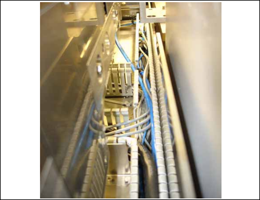
13.4.3 Cable and hose laying PA2
O Route the cables in the cable duct to the conversion boards of the PCB conveyor.
Fig. 148
13
Assembly Instructions PCB Stopper Single Conveyor SIPLACE S-27HM / HS-60 / D4 / D3 / HF- / X-Series
Edition 06/2007
173
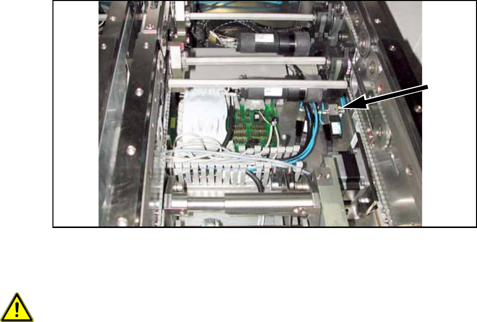
O Stow the cables in the wide cable duct next to the conversion boards.
13
13
Fig. 149
O Connect both air pressure supply hoses (PUN 3) with both magnetic valves.
O Stick the valves onto the mounting tub with double-sided adhesive tape as shown in the figure.
13
13
Make sure that no cables, hoses or valves touch the belt of the width adjustment. 13
13
13
Solenoid
valve
Assembly Instructions PCB Stopper Single Conveyor SIPLACE S-27HM / HS-60 / D4 / D3 / HF- / X-Series
Edition 06/2007
174
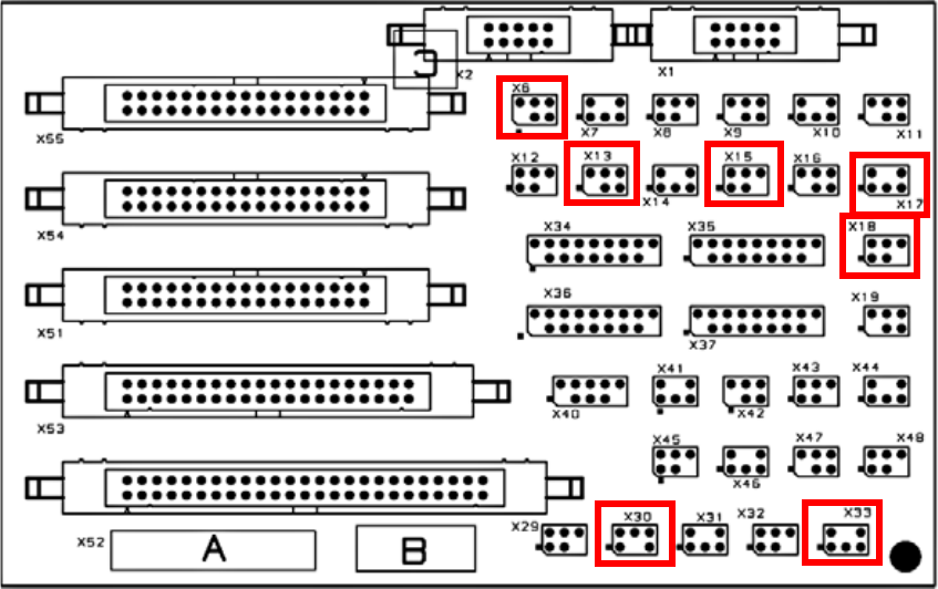
O Plug the connectors of the connecting lines onto the conversion board according to the wiring
plan.
O Plug the coded plug onto location X6 on the conversion board for both conveyors.
Fig. 150 Terminal diagram for conversion board of PCB conveyor