SussPA300UserGuide.pdf - 第11页
10 SUSS / PA300 / User Manual / M10-121841-00 / February 2002 2.9 Ergonomic Information Note The user should take into consideration the ergonomic conditions according to the demands of SEMI and should refer to the ergon…
SUSS / PA300 / User Manual / M10-121841-00 / February 2002
9
2.6 Thermal Precautions
The prober may optionally be equipped with a thermal chuck. These chucks operate at
very low and high temperatures that will burn the user upon contact. Avoid touching
during operation. The use of vacuum forceps is recommended. The accompanying
manual should be read thoroughly before the thermal chuck is used and safety
instructions should be taken into consideration.
2.7 Risk Valuation
The following risks correspond to KSD risk valuation categories.
Reaching in during normal operation is not necessary.
Reaching in with a bare hand in the case of a default without stopping the system does
not produce any immediate danger the moving parts are restricted and therefore unable
to squash anything inside.
The movement of energy chains is relatively slow. As the chain links can turn off,
reaching into the rear side of the energy chains does not produce any particular danger.
In the interest of positional accuracy, touching the energy chains during operation
should be avoided.
2.8 User Information
It should be noted that the position of the system is important where safety is concerned.
If SUSS recommendations are considered and followed injury risks can be kept minimal.
No supervision of chemicals etc. is required. But better safety for the energy chains
can be reached by using a SUSS cover which can be ordered along with the system.

10
SUSS / PA300 / User Manual / M10-121841-00 / February 2002
2.9 Ergonomic Information
Note The user should take into consideration the ergonomic conditions
according to the demands of SEMI and should refer to the ergonomic
information table in the appendix. It is the responsibility of the customer
to ensure that these requirements are met.
Transient overvoltage as per overvoltage category II
Vacuum supply should be less than 200 mbar absolute – less than 0.8 bar gauge.
Air – Pressure supply: Filtered, dry and oil free air of at least 4 bar.
Maximum pressure is 10 bar.
Pollution Degree: Grade 1 as per IEC 664
Usage Position: Probe Station – horizontal.
Electronics Prober Bench – horizontal.
2.9.1 Clearances
Clearance suggestions and measurements for fingers, hands, arms, legs and the whole
body are given in the appendix (Ergonomic Information Table). SEMI has provided
these guidelines in order to make access and maintenance easier, thus creating a
safer working environment.
2.9.2 Display Units
Suggestions and measurements for the display units and installation variants are given
in the appendix (Ergonomic Information Table). SEMI has provided these guidelines
in order to make access and maintenance easier, thus creating a safer working
environment.
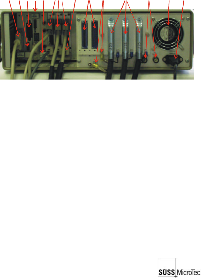
2.10 Connections
Functional Ground Terminals: (see photo overleaf)
Functional Ground Terminal for grounding conductor from Electronics Rack
1 free terminal for functional contact
4 free earth terminals to ground the 4 probeheads
1 free terminal connecting to the platen functional contact
2 connections for functional contact
SUSS / PA300 / User Manual / M10-121841-00 / February 2002
11
Main microc
o
n
t
r
o
l
l
e
r
b
o
a
r
d
Misc. Outpu
t
i
n
t
e
r
f
a
c
e
c
a
r
d
(
C
4
)
Main fuses
(
F
1
/
F
2
)
Functional G
r
o
u
n
d
T
e
r
m
i
n
a
l
s
Main power
s
u
p
p
l
y
Motorized P
r
o
b
e
H
e
a
d
s
(
1
e
a
c
h
)
Control (end
l
i
m
i
t
s
,
e
n
c
o
d
e
r
signals, LED
s
)
ControlBox
i
n
t
e
r
f
a
c
e
Reserve so
c
k
e
t
s
f
o
r
m
o
t
o
r
i
z
e
d
t
u
r
r
e
t
/
options i.e.:
A
u
t
o
m
a
t
i
c
p
r
o
b
e
r
i
n
p
u
t
s
Power supp
l
y
s
o
c
k
e
t
s
(
x
3
)
IEEE
Prober conn
e
c
t
i
o
n
s
Address Sw
i
t
c
h
Extractor fa
n
Electronics Rack: (see above)
Mains cable (3 prong)
3 electrical control cables to the probe station (plus 2 spare)
Ground terminal to the probe station
Probe Station:
Inputs (on the rear side on the right of double side probe machines and on the right
hand side at the back of standard machines)
3 electrical control cables to the electronics rack
1 vacuum inlet
1 compressed air inlet
Cover switch (interlock function)
Chuck potential; max. 120 VDC (isolated from system)
System potential; one additional on base frame on left hand side of bridge.