SussPA300UserGuide.pdf - 第12页
SUSS / PA300 / User Manual / M10-121841-00 / February 2002 11 M a i n m i c r o c o n t r o l l e r b o a r d M i s c . O u t p u t i n t e r f a c e c a r d ( C 4 ) M a i n f u s e s ( F 1 / F 2 ) F un c t i on a l G r …

10
SUSS / PA300 / User Manual / M10-121841-00 / February 2002
2.9 Ergonomic Information
Note The user should take into consideration the ergonomic conditions
according to the demands of SEMI and should refer to the ergonomic
information table in the appendix. It is the responsibility of the customer
to ensure that these requirements are met.
Transient overvoltage as per overvoltage category II
Vacuum supply should be less than 200 mbar absolute – less than 0.8 bar gauge.
Air – Pressure supply: Filtered, dry and oil free air of at least 4 bar.
Maximum pressure is 10 bar.
Pollution Degree: Grade 1 as per IEC 664
Usage Position: Probe Station – horizontal.
Electronics Prober Bench – horizontal.
2.9.1 Clearances
Clearance suggestions and measurements for fingers, hands, arms, legs and the whole
body are given in the appendix (Ergonomic Information Table). SEMI has provided
these guidelines in order to make access and maintenance easier, thus creating a
safer working environment.
2.9.2 Display Units
Suggestions and measurements for the display units and installation variants are given
in the appendix (Ergonomic Information Table). SEMI has provided these guidelines
in order to make access and maintenance easier, thus creating a safer working
environment.
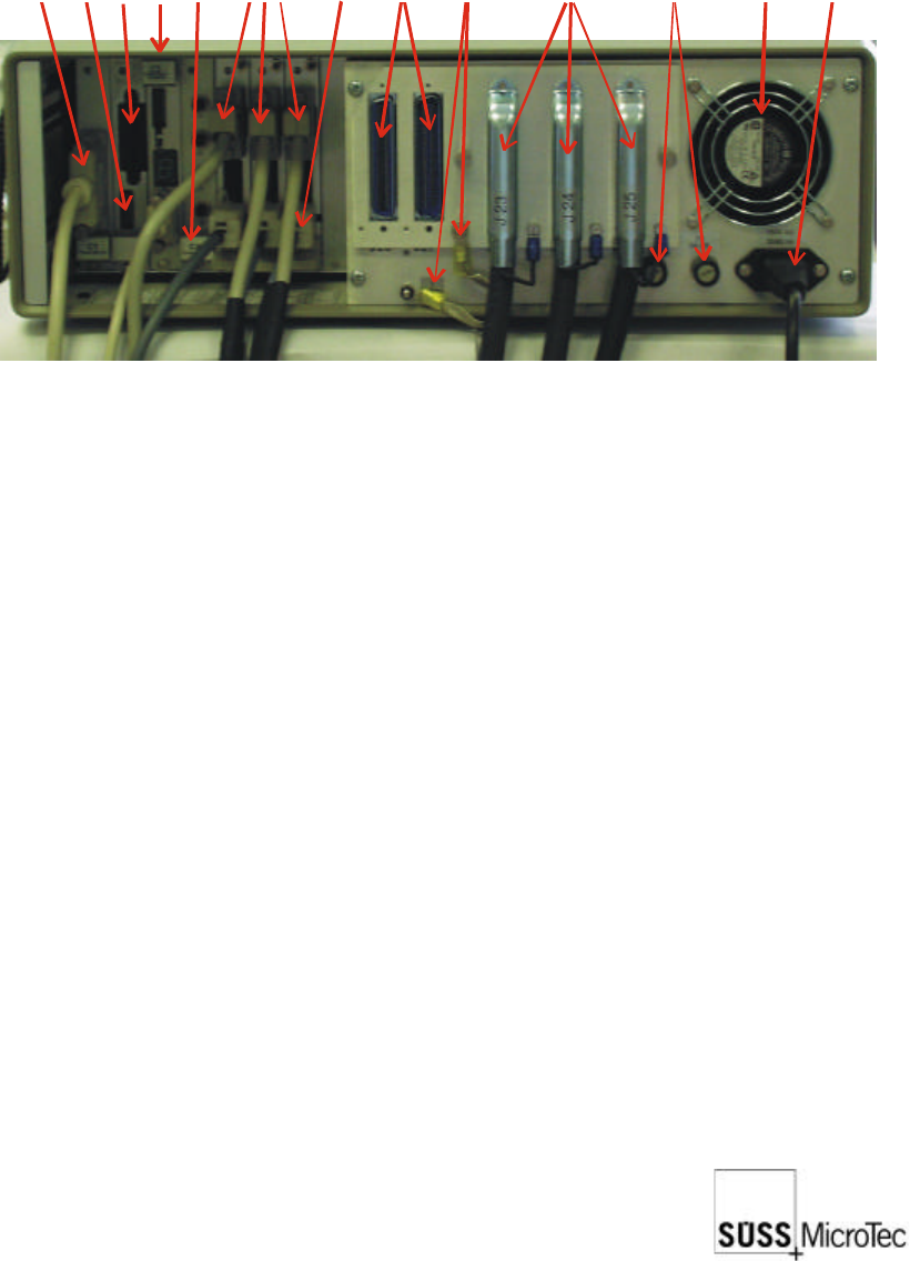
2.10 Connections
Functional Ground Terminals: (see photo overleaf)
Functional Ground Terminal for grounding conductor from Electronics Rack
1 free terminal for functional contact
4 free earth terminals to ground the 4 probeheads
1 free terminal connecting to the platen functional contact
2 connections for functional contact
SUSS / PA300 / User Manual / M10-121841-00 / February 2002
11
Main microc
o
n
t
r
o
l
l
e
r
b
o
a
r
d
Misc. Outpu
t
i
n
t
e
r
f
a
c
e
c
a
r
d
(
C
4
)
Main fuses
(
F
1
/
F
2
)
Functional G
r
o
u
n
d
T
e
r
m
i
n
a
l
s
Main power
s
u
p
p
l
y
Motorized P
r
o
b
e
H
e
a
d
s
(
1
e
a
c
h
)
Control (end
l
i
m
i
t
s
,
e
n
c
o
d
e
r
signals, LED
s
)
ControlBox
i
n
t
e
r
f
a
c
e
Reserve so
c
k
e
t
s
f
o
r
m
o
t
o
r
i
z
e
d
t
u
r
r
e
t
/
options i.e.:
A
u
t
o
m
a
t
i
c
p
r
o
b
e
r
i
n
p
u
t
s
Power supp
l
y
s
o
c
k
e
t
s
(
x
3
)
IEEE
Prober conn
e
c
t
i
o
n
s
Address Sw
i
t
c
h
Extractor fa
n
Electronics Rack: (see above)
Mains cable (3 prong)
3 electrical control cables to the probe station (plus 2 spare)
Ground terminal to the probe station
Probe Station:
Inputs (on the rear side on the right of double side probe machines and on the right
hand side at the back of standard machines)
3 electrical control cables to the electronics rack
1 vacuum inlet
1 compressed air inlet
Cover switch (interlock function)
Chuck potential; max. 120 VDC (isolated from system)
System potential; one additional on base frame on left hand side of bridge.
12
SUSS / PA300 / User Manual / M10-121841-00 / February 2002
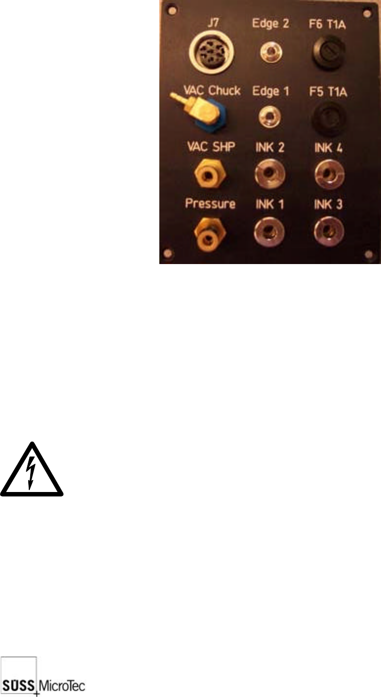
2.11 Utility Distribution
Exits:
VAC CHUCK: Vacuum exit for the chuck
VAC SHP: Vacuum exit for the probe head platen
INK 1...INK4: 4 Inker exits (each roughly 24V)
J7: Optional 24V or 5V power supply
Entrances:
EDGE 1...2: 2 Edge sensors
INK and EDGE leads are low voltage. For safety reasons, the low voltage leads
should be isolated. These should not be touched during operation.