SussPA300UserGuide.pdf - 第22页
SUSS / PA300 / User Manual / M10-121841-00 / February 2002 21 4.2.6 Accessories Accessories such as the computer table, control panel and mouse should be supplied by the customer. For suggestions, measurements and furthe…

20
SUSS / PA300 / User Manual / M10-121841-00 / February 2002
4.2.4 Open Connections
In order to make safe connections, the device must not be connected to the mains.
The probe system can be equipped with a wide range of accessories and options,
each with its own electrical interconnects. All plugs and connectors of SUSS
manufactured equipment are designed to prevent incorrect connections. Exercise extra
care when connecting other components. Generally all plugs and jacks will have number
or function labels to match up. The strapping wires should be mounted properly and
laid so that accidents can be ruled out.
Note: Unused jump cables must not be used for anything else.
Minimum Connections
These connections are required on a system with no additional options or accessories
(not including power connections):
a. Electronics rack to probe station: Grounding (green/yellow) conductor.
b. Electronics rack to mechanics: 3 large cables and connectors, mounted on a
common plate (2 optional).
c. Electronics rack to joystick controller - RS232 standard cable.
d. Electronics rack to computer (PC) - RS232 standard cable.
e. Computer (PC) to monitor, keyboard and mouse (if system is equipped with
one).
Note: Please refer to the Ergonomic Information table in the appendix for
possible dimensions.
Other Typical Connections
a. Electronics rack to motorized probeheads, edge and contact sense.
b. Electronics rack to microscope illuminator
c. Camera to computer (PC) or a second monitor.
4.2.5 Loading Lid with Interlock
The interlock stops all motorized axis from moving when the loading lid is opened.
(Motor power is interrupted). Once the lid is closed, the motors are re-enabled and
ready to perform the next movement command.
Opening the loading lid during mechanical stage movement will cause it to stop
after one second. This procedure should not affect the main control program.
SUSS / PA300 / User Manual / M10-121841-00 / February 2002
21
4.2.6 Accessories
Accessories such as the computer table, control panel and mouse should be supplied
by the customer. For suggestions, measurements and further optional devices please
see the Ergonomic Information Table in the appendix.
When computer monitors are to be used, the size is to be determined by the customer
(see Ergonomic Information Table in the appendix).
The customer must also determine the location of the hand controls and whether the
machine is to be used in a standing or sitting position (see Ergonomic Information
Table in the appendix).
4.3 Emergency Off (EMO) System
See section 7.2.2
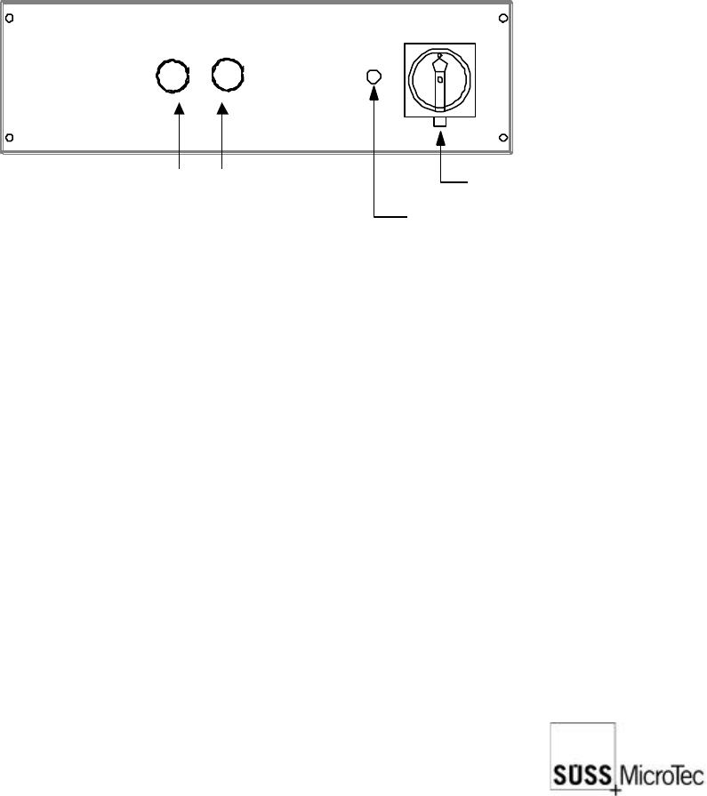
4.3.1 Main Power Switch on Electronics Rack
The main power switch on the electronics rack is also an EMO system. This is shown
through a red grip on a yellow background. After use all movement is stopped and the
system is completely without power. Positions are lost and the system must be re-
initialized.
Main Power Switch (EMO)
Power On Lamp
On Button (green)
Off Button (red)
4.3.2 EMO Switch on Probe Station
The EMO system when activated immediately stops all system movement and removes
all small voltages except the 24 VAC EMO power supply.
The EMO button is for emergency use only to prevent injury, or damage to equipment
or the device under test. Normal shutdown of the system saves positioning information
that is used during the next system power-up. The use of the EMO system may corrupt
the positioning information. Running the Prober Initialization program will be necessary
for normal system operation to be restored. Please refer to the ProberBench manual.
The standard EMO actuator is red on a yellow background and is located on the right
front corner of the mechanic. Optional buttons may be located on a light tight enclosure,
isolation table or instrument rack. After use, latching buttons should be released by
pulling outward on the button, and the system can then be switched on again by pushing
the green button on the ProberBench electronics
22
SUSS / PA300 / User Manual / M10-121841-00 / February 2002
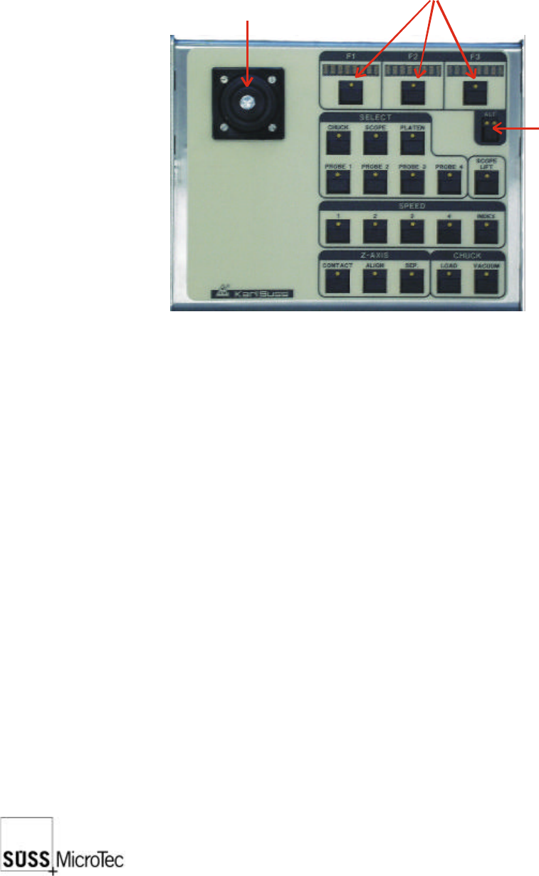
4.4 Joystick Controller
For further explanation please refer to section 7.3.
The Joystick Controller provides remote control of all probe system motorized stages
including the wafer chuck, microscope, ProbeHeads and platen. The most common
functions such as load, vacuum, go and set home, contact and two-point alignment
are also provided. It can be used with or without a PC.
Joystick
(X, Y movement of
chuck or scope)
Mode key
Position & function displays