SussPA300UserGuide.pdf - 第20页
SUSS / PA300 / User Manual / M10-121841-00 / February 2002 19 4.2.2 Non-electrical Utilities Connect vacuum and air or nitrogen at the right rear corner of the mechanics: Fuses Optional 24V / 5V power supply Compressed a…
18
SUSS / PA300 / User Manual / M10-121841-00 / February 2002
4.2 The Basic Prober
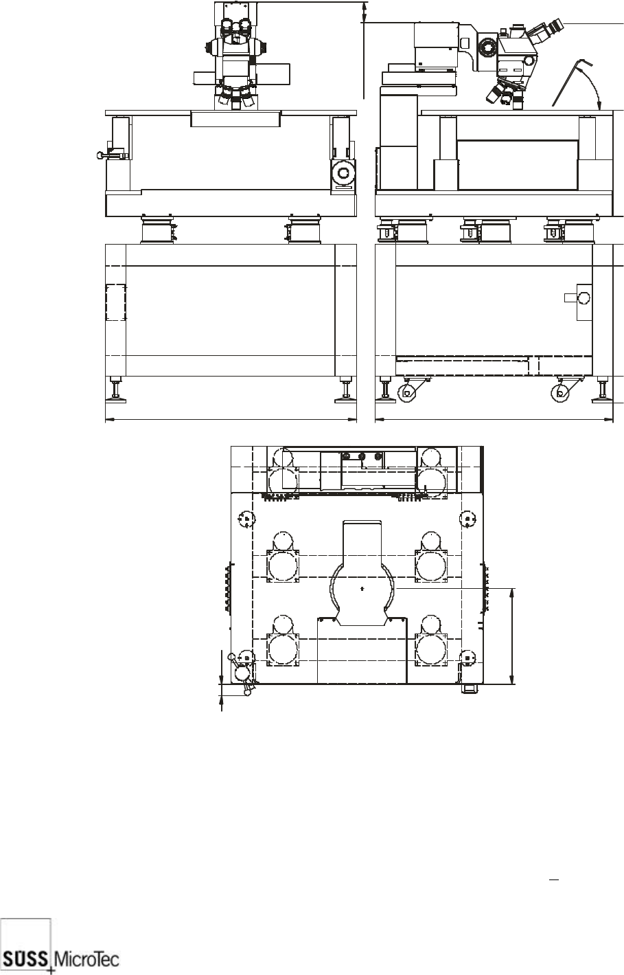
4.2.1 System Dimensions
System height is with microscope in raised position.
System depth is with microscope in full rearward position.
For laser cutter add 305 mm to the height.
For camera add camera height, plus 64 mm for camera adapter to the height.
The table and the device stand on 4 positional points in the four corners, each carrying
200kg. The centre of gravity falls nearly in the centre, moving about +100 mm in both
the X and Y directions.
950
1107
705
900
Z travel 80 (130)
0
100
518
598
1434
43
360
6
0
°
SUSS / PA300 / User Manual / M10-121841-00 / February 2002
19
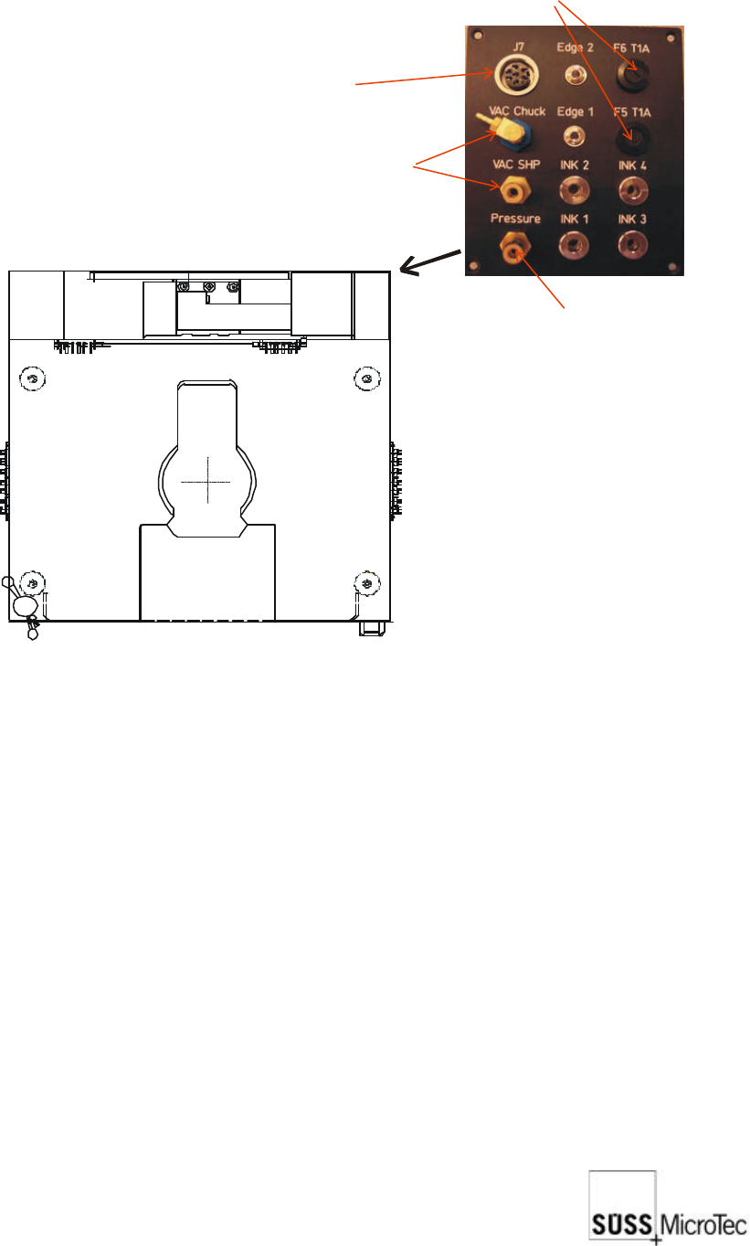
4.2.2 Non-electrical Utilities
Connect vacuum and air or nitrogen at the right rear corner of the mechanics:
Fuses
Optional 24V /
5V power supply
Compressed air
Vacuum connections
for chuck and platen
Ground
EMO
Ground x2
4.2.3 Electrical Utilities
All components that require AC power input will be labelled with the required input
voltage and VA or wattage. Ensure all AC power outlets are correct.
Components that require AC power include:
a. Electronics rack
b. Microscope illuminator
c. Computer (PC) and monitor
d. Camera power supply
Review the Installation Checklist in the appendix and apply power to all components.

20
SUSS / PA300 / User Manual / M10-121841-00 / February 2002
4.2.4 Open Connections
In order to make safe connections, the device must not be connected to the mains.
The probe system can be equipped with a wide range of accessories and options,
each with its own electrical interconnects. All plugs and connectors of SUSS
manufactured equipment are designed to prevent incorrect connections. Exercise extra
care when connecting other components. Generally all plugs and jacks will have number
or function labels to match up. The strapping wires should be mounted properly and
laid so that accidents can be ruled out.
Note: Unused jump cables must not be used for anything else.
Minimum Connections
These connections are required on a system with no additional options or accessories
(not including power connections):
a. Electronics rack to probe station: Grounding (green/yellow) conductor.
b. Electronics rack to mechanics: 3 large cables and connectors, mounted on a
common plate (2 optional).
c. Electronics rack to joystick controller - RS232 standard cable.
d. Electronics rack to computer (PC) - RS232 standard cable.
e. Computer (PC) to monitor, keyboard and mouse (if system is equipped with
one).
Note: Please refer to the Ergonomic Information table in the appendix for
possible dimensions.
Other Typical Connections
a. Electronics rack to motorized probeheads, edge and contact sense.
b. Electronics rack to microscope illuminator
c. Camera to computer (PC) or a second monitor.
4.2.5 Loading Lid with Interlock
The interlock stops all motorized axis from moving when the loading lid is opened.
(Motor power is interrupted). Once the lid is closed, the motors are re-enabled and
ready to perform the next movement command.
Opening the loading lid during mechanical stage movement will cause it to stop
after one second. This procedure should not affect the main control program.