SussPA300UserGuide.pdf - 第33页
32 SUSS / PA300 / User Manual / M10-121841-00 / February 2002 7.3 Joystick Controller The Joystick Controller provides remote control of all probe system motorized stages including wafer chuck, microscope, probeheads and…
SUSS / PA300 / User Manual / M10-121841-00 / February 2002
31
7.2.1 System Power-Up
System power-up prepares the prober for use from the Joystick Controller and the
User Interface.
1. Rotate the Electronics Rack Main Power Switch to the On position. The green
lamp will light indicating power to the electronics and the EMO System. Press the
green On button. The integral green lamp will light. If the lamp is not lit, ensure the
latching EMO button on the mechanic is in the released position.
Note: The boot up sequence of the User Interface, running on the PC,
includes establishing communications with the Electronics Rack.
Therefore the electronics must be on before starting the User Interface
to prevent a communications error.
If an error occurs, turn on the electronics and click OK in the error message box.
2. Turn on power to the PC, monitor and all ancillary equipment, such as the
microscope illuminator, laser cutter and camera.
3. The system is now ready for use with the Joystick Controller or from Microsoft
Windows
®
.
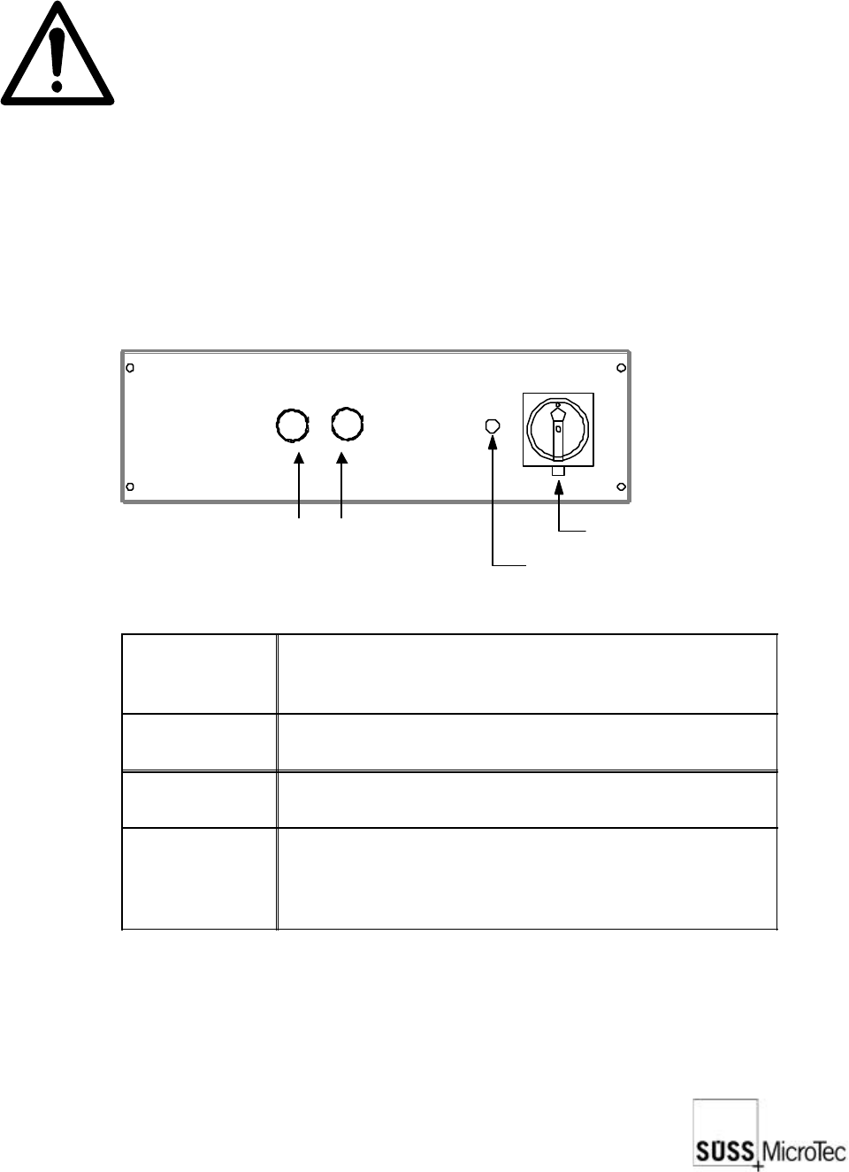
7.2.2 Controls and Functions
Main Power Switch (EMO)
Power On Lamp
On Button (green)
Off Button (red)
EMO Main
Power Switch
Applies power to the electronics rack and to the EMO
system. Power is supplied to the entire system by
pressing the On button.
Power On
Lamp
Illuminated when the Main Power Switch is on and the
specified line voltage is present.
Off Button
Stops all machine movement and removes all
voltages except the 24 VAC EMO power supply.
On Button
Used to energize the EMO system to apply power to
the probe system. The integral green lamp is lit when
the system is ready for use. The EMO Main Power
Switch must be on for the On button to be operable.
32
SUSS / PA300 / User Manual / M10-121841-00 / February 2002
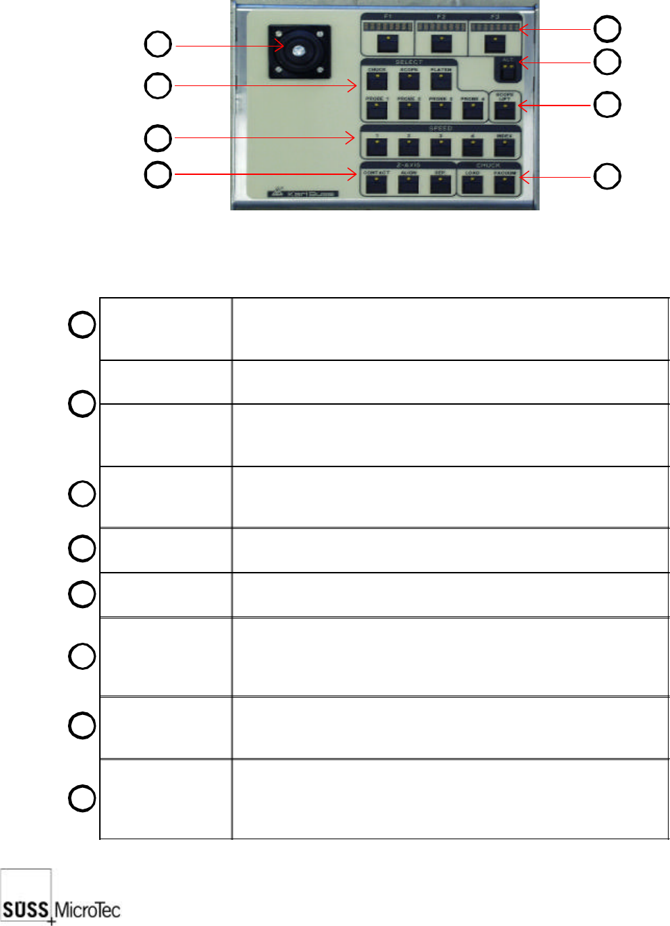
7.3 Joystick Controller
The Joystick Controller provides remote control of all probe system motorized stages
including wafer chuck, microscope, probeheads and platen. The most common
functions, such as load, vacuum, go and set home and contact and two-point alignment
are also provided. It can be used with or without a PC.
Joystick
Used to move motorized stages in the X and Y axes. The joystick
provides proportional control based on the amount of joystick
deflection.
LED Displays (3x)
Indicates the use of the F1-F3 function key below it and updates
each time the Alt key is pressed.
F1-F3 Function
Keys
Used in conjunction with the Alt Key to provide 12 additional
functions. Pressing the key will either carry out the function or
redefine the keys with new functions.
Alt Key
A four-state key as indicated by its LEDs: off-off, off-on, on-off and
on-on. Each press of the Alt key will display the next three functions
in the LED displays.
Lift Key
Raises the microscope to change objectives or facilitate setup. The
LED is lit when the microscope is up.
Select Keys (7x)
Defines the stage to be controlled by the joystick and which stage
the function keys relate to.
Speed Keys (5x)
Sets the speed at which stages move in response to the joystick.
Speed 1: jogs or moves at the smallest stepping increment
Speed 2-4: each cover a speed range (4 = 100%)
Index: moves at a user-defined index value in X or Y direction.
Z-Axis Keys (3x)
Moves the selected stage or probehead to the defined contact, align
and separate positions. Contact must be set by the user before
these keys are operational.
Chuck Keys (2x)
Load lowers the chuck to the lowest or load position, centers in the
X axis and forward towards the user.
Vacuum controls the vacuum to the chuck stage for securing the
wafer or DUT.
1
1
2
3
4
5
6
7
8
2
3
4
8
7
6
5

SUSS / PA300 / User Manual / M10-121841-00 / February 2002
33
7.3.1 Getting Started
This procedure guides the user through a typical set-up, from powering up the system
to aligning theta, setting contact and home, and entering an index.
1. Turn on the power to all components, as detailed in System Power-Up.
2. On the Joystick Controller select the stage to be used: chuck, microscope, platen
or probehead. For this example, the chuck is selected.
3. Select the control speed, typically Speed 4 at a low magnification to locate the
probe tips and target.
4. Press the ALT Key for the Z-axis controls; the right LED is lit. If the chuck is not in
the loading position (front middle), move the chuck there with the joystick. Load
the wafer on the pins and switch on the vacuum. Press Z UP until the wafer is lying
on the chuck in the center.
5. Ensure the platen is in the contact position and raise the chuck, using Z UP and Z
DOWN keys, F2 and F3, so the wafer or DUT is about 1-2 mm from the platen or
probecard. This allows the use of short probe tips and places the wafer within the
working range of probeheads. Press SET CONT, F1 to set contact at this point.
6. Since the chuck will not move while in contact, press Z-Axis Align to lower the
chuck.
7. Use the joystick and microscope focus to get the wafer and probe tips in view. If
equipped with motorized focus Z-axis controls, operate the focus when the
microscope is selected.
8. Press the ALT Key for Align, no are LED’s lit and F3. For a two-point alignment
position the wafer stage near the left (right) edge of the wafer and a horizontal
street or feature is aligned with a crosshair or probe tip reference point. Press
MARK 1. Move to the right (left) edge of the wafer and align with the same street or
feature and press MARK 2. The chuck theta then rotates to correct the rotational
error. Increased magnification and careful alignment increase accuracy. For probing
packaged parts, use the microscope software theta compensation.
9. Position the wafer chuck at the first test point and press SET HOME, Alt Key and
F3.
10. Press Z-Axis Contact to raise the chuck to contact position. Position all probes and
lower to contact.
11. The joystick and Z-Axis controls can now be used to move to more test points. An
index can be set with Alt Key, left LED lit and F3. The F1 and F2 Displays indicate
the index value. Change the index using the joystick and press F1 and F2 to enter.
12. Unloading: With Z DOWN, lower the chuck until it stops. Move chuck to the loading/
unloading position and switch off vacuum (“VAC”). Press Z DOWN until it will not
go further and remove the wafer from the pins.