SussPA300UserGuide.pdf - 第19页
18 SUSS / PA300 / User Manual / M10-121841-00 / February 2002 4.2 The Basic Prober 4.2.1 System Dimensions System height is with microscope in raised position. System depth is with microscope in full rearward position. F…
SUSS / PA300 / User Manual / M10-121841-00 / February 2002
17
4 Main Components of the System
4.1 Typical System Data
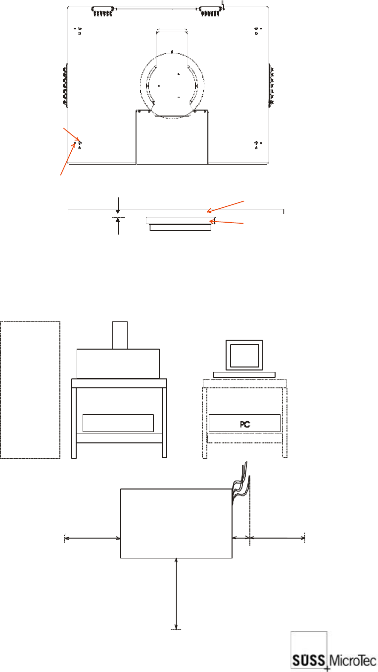
Set screw
Levelling screw
* the gap will be 2 mm if your system is equipped for HF or doubleside measurements or with a thermo chuck
Platen
Chuck
1 mm gap*
optional
measuring
units
Pa300 with table
Monitor
Electronics
Keyboard,
mouse &
panel
Front view
Top view Pa300
200
600* 600*
800
*For installation only
Cable
connection
location
Table: W x D x H
= 800 x 800 x 750 mm
18
SUSS / PA300 / User Manual / M10-121841-00 / February 2002
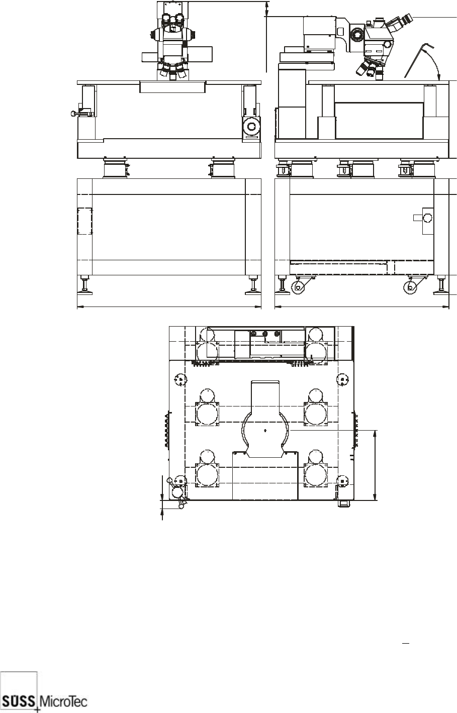
4.2 The Basic Prober
4.2.1 System Dimensions
System height is with microscope in raised position.
System depth is with microscope in full rearward position.
For laser cutter add 305 mm to the height.
For camera add camera height, plus 64 mm for camera adapter to the height.
The table and the device stand on 4 positional points in the four corners, each carrying
200kg. The centre of gravity falls nearly in the centre, moving about +100 mm in both
the X and Y directions.
950
1107
705
900
Z travel 80 (130)
0
100
518
598
1434
43
360
6
0
°
SUSS / PA300 / User Manual / M10-121841-00 / February 2002
19
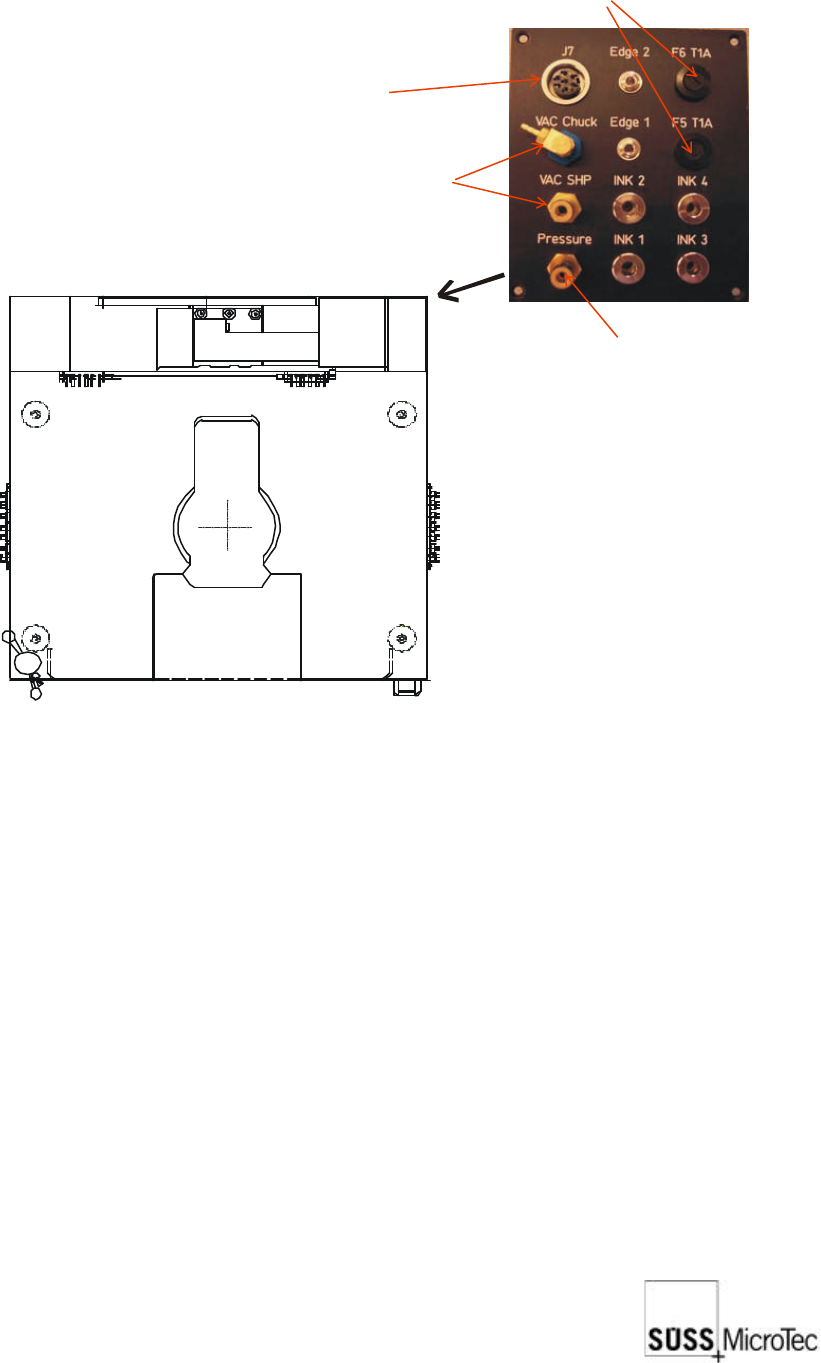
4.2.2 Non-electrical Utilities
Connect vacuum and air or nitrogen at the right rear corner of the mechanics:
Fuses
Optional 24V /
5V power supply
Compressed air
Vacuum connections
for chuck and platen
Ground
EMO
Ground x2
4.2.3 Electrical Utilities
All components that require AC power input will be labelled with the required input
voltage and VA or wattage. Ensure all AC power outlets are correct.
Components that require AC power include:
a. Electronics rack
b. Microscope illuminator
c. Computer (PC) and monitor
d. Camera power supply
Review the Installation Checklist in the appendix and apply power to all components.