SussPA300UserGuide.pdf - 第42页
SUSS / PA300 / User Manual / M10-121841-00 / February 2002 41 8.5 Preventive Maintenance The PA300 requires minimal preventive maintenance. In general, care should be taken to keep the system clean and covered when not i…
40
SUSS / PA300 / User Manual / M10-121841-00 / February 2002
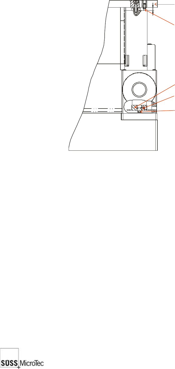
1. Loosen the set screw in the four corners of the platen, then move the chuck Z-Axis
to its highest position and the platen to its lowest position.
2. Use feeler gauges to check the gap between the chuck and the platen at four
places around the center opening. The gap should be 1 mm ± 0.05 mm.
3. If adjustment of one or more corners is required, loosen the appropriate lock screw(s)
and raise or lower the corner(s) using the adjusting screw.
4. Repeat the measurements since adjusting one corner usually affects the others.
5. When the adjustment is complete, tighten the lock screws and reset all four set
screws.
8.4.3 Chuck Stage Z Axis End Limit Sensor Adjustment
The chuck stage Z axis end limit sensors are accurately adjusted before leaving the
factory. If they should need readjusting, please contact your local SUSS Service
department for more details.
8.4.4 Microscope Stage Pneumatic Up/Down Adjustment
The motion of the microscope should be smooth and precise to avoid causing excessive
shock to the system.
1. Remove the sheet metal stage cover.
2. Adjust the main incoming pressure regulator located next to the cylinder to ensure
that a minimum of 4 bar is available.
3. Individually adjust the up and down speeds using the cylinder incoming throttle for
the up direction and the cylinder exhaust throttle for the down direction. The up
speed can be slightly faster than the down speed.
8
Platen
Set screw
Lock screw
Chain
Adjustment screw

SUSS / PA300 / User Manual / M10-121841-00 / February 2002
41
8.5 Preventive Maintenance
The PA300 requires minimal preventive maintenance. In general, care should be taken
to keep the system clean and covered when not in use (e.g. overnight) and the following
periodic cleaning and lubrication procedures should be performed at the recommended
intervals.
Only a SUSS Field Service Representative or SUSS trained personnel should carry
out preventive maintenance.
8.5.1 Annual Operational Check
1. Remove, disassemble, and clean covers and adjust the planarity of the chuck and
the microscope.
2. Inspect all moving parts; clean and lubricate where necessary.
3. Check all basic adjustments including software compensation.
8.5.2 Lubrication
A list of parts which require lubrication and the recommended lubrication intervals
(assuming eight (8) hours per day operation) are shown below. The specified grease
is Kluber NBU 8 EP; the specified oil is a resin-free precision machine oil, such as
Custanol F. These products can also be purchased from Karl Suss.
Point of Lubrication Interval Lubricant
Microscope stage spindles 1 year grease
Microscope stage bearing rails 1 year grease
Chuck X-Y stage drive spindles 12 weeks grease
Chuck Z axis bearing rails 4 weeks oil
Please note that it is also possible to sign a separate contract with SUSS MicroTec for
these maintenance procedures. Please contact your SUSS Service Department for
further details. Contact information can be found at the front of this manual.

42
SUSS / PA300 / User Manual / M10-121841-00 / February 2002
9 Troubleshooting
Each section starts with the problem or fault that is occurring. Work through the list of
possible causes and solutions until the problem is corrected. If the problem is not
resolved with this information contact SUSS Customer Service. In principle, Repairs
can only be carried out by SUSS Personnel. Contact details are in the front of this
manual or listed in the ProberBench User Interface under “Help and Contacting
Customer Service”.
9.1 System Does Not Power-Up
Check that:
1. Power, at the specified voltage and VA or watts, is supplied to the system.
2. Main Power Switch is on and the Indicator Lamp is lit.
3. On button has been pressed and its green lamp is illuminated.
4. Latching EMO Off button is in released position.
5. Electronics Rack main fuses are good. EMO power fuses are good (internal fuses)
9.2 Mechanics Do Not Respond to the Joystick Controller
Check that:
1. Mechanic responds to the User Interface.
2. The three LED function displays are on.
3. Controller is plugged into the Electronics Rack.
4. Loading lid is closed
9.3 Mechanics Do Not Respond to the User Interface (PC)
Check that:
1. Mechanic responds to the Joystick Controller.
2. User Interface is in demo mode.
3. Communications Error reported by a Dialog Box.
9.4 Stages Do Not Position Correctly
Check that:
1. Stage centers correctly.
2. Run Prober Initialization Program.