SussPA300UserGuide.pdf - 第41页
40 SUSS / PA300 / User Manual / M10-121841-00 / February 2002 1. Loosen the set screw in the four corners of the platen, then move the chuck Z-Axis to its highest position and the platen to its lowest position. 2. Use fe…
SUSS / PA300 / User Manual / M10-121841-00 / February 2002
39
2. Planarization can be measured with a dial indicator or with the microscope. This
procedure will rely on the microscope, which when used with a 50x objective (500x
total magnification) provides a 2 micron depth of focus.
3. The chuck level will be checked near the edge of the chuck and in-line with each
levelling screw, which are approximately at each corner. You can move to these
positions with the joystick or enter the positions in a TableView file and click on
each site to quickly move to it.
4. Move to each of the three sites and determine which one is the lowest by noting if
the microscope was raised or lowered to focus. The lowest will be the reference
point (site #1) to which the other two will be adjusted. The lowest is used to maintain
maximum spring pressure of the levelling mechanism.
Note: Planarization is done with the chuck surface, not a wafer which may
not be planar.
5. Move to site #1 and focus using the microscope.
6. Move to site #2 and adjust the chuck levelling screw at this site so the chuck is in
focus. Do not focus using the microscope.
7. Move to site #3 and adjust the chuck levelling screw at this site so the chuck is in
focus. Do not focus using the microscope.
8. Repeat steps 5 through to 7 until all three sites remain in focus.
9. Reinstall stage covers.
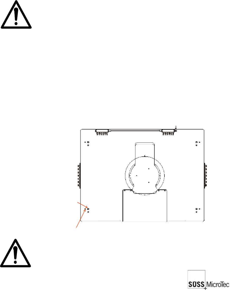
8.4.2 Platen Levelling Procedure
Set screw
Levelling screw
Note: This procedure should be performed only after the chuck has been
properly planarized or levelled.
40
SUSS / PA300 / User Manual / M10-121841-00 / February 2002
1. Loosen the set screw in the four corners of the platen, then move the chuck Z-Axis
to its highest position and the platen to its lowest position.
2. Use feeler gauges to check the gap between the chuck and the platen at four
places around the center opening. The gap should be 1 mm ± 0.05 mm.
3. If adjustment of one or more corners is required, loosen the appropriate lock screw(s)
and raise or lower the corner(s) using the adjusting screw.
4. Repeat the measurements since adjusting one corner usually affects the others.
5. When the adjustment is complete, tighten the lock screws and reset all four set
screws.
8.4.3 Chuck Stage Z Axis End Limit Sensor Adjustment
The chuck stage Z axis end limit sensors are accurately adjusted before leaving the
factory. If they should need readjusting, please contact your local SUSS Service
department for more details.
8.4.4 Microscope Stage Pneumatic Up/Down Adjustment
The motion of the microscope should be smooth and precise to avoid causing excessive
shock to the system.
1. Remove the sheet metal stage cover.
2. Adjust the main incoming pressure regulator located next to the cylinder to ensure
that a minimum of 4 bar is available.
3. Individually adjust the up and down speeds using the cylinder incoming throttle for
the up direction and the cylinder exhaust throttle for the down direction. The up
speed can be slightly faster than the down speed.
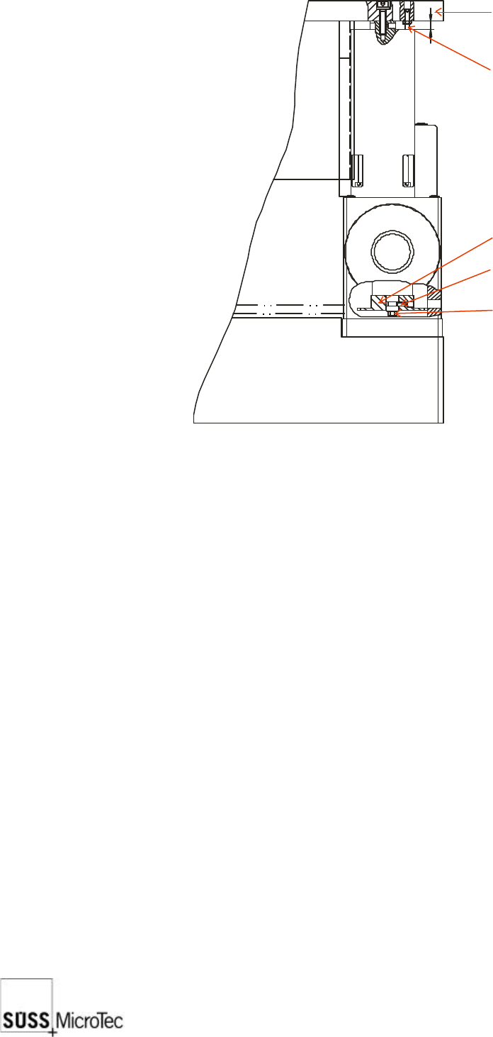
8
Platen
Set screw
Lock screw
Chain
Adjustment screw

SUSS / PA300 / User Manual / M10-121841-00 / February 2002
41
8.5 Preventive Maintenance
The PA300 requires minimal preventive maintenance. In general, care should be taken
to keep the system clean and covered when not in use (e.g. overnight) and the following
periodic cleaning and lubrication procedures should be performed at the recommended
intervals.
Only a SUSS Field Service Representative or SUSS trained personnel should carry
out preventive maintenance.
8.5.1 Annual Operational Check
1. Remove, disassemble, and clean covers and adjust the planarity of the chuck and
the microscope.
2. Inspect all moving parts; clean and lubricate where necessary.
3. Check all basic adjustments including software compensation.
8.5.2 Lubrication
A list of parts which require lubrication and the recommended lubrication intervals
(assuming eight (8) hours per day operation) are shown below. The specified grease
is Kluber NBU 8 EP; the specified oil is a resin-free precision machine oil, such as
Custanol F. These products can also be purchased from Karl Suss.
Point of Lubrication Interval Lubricant
Microscope stage spindles 1 year grease
Microscope stage bearing rails 1 year grease
Chuck X-Y stage drive spindles 12 weeks grease
Chuck Z axis bearing rails 4 weeks oil
Please note that it is also possible to sign a separate contract with SUSS MicroTec for
these maintenance procedures. Please contact your SUSS Service Department for
further details. Contact information can be found at the front of this manual.