SussPA300UserGuide.pdf - 第34页
SUSS / PA300 / User Manual / M10-121841-00 / February 2002 33 7.3.1 Getting Started This procedure guides the user through a typical set-up, from powering up the system to aligning theta, setting contact and home, and en…
32
SUSS / PA300 / User Manual / M10-121841-00 / February 2002
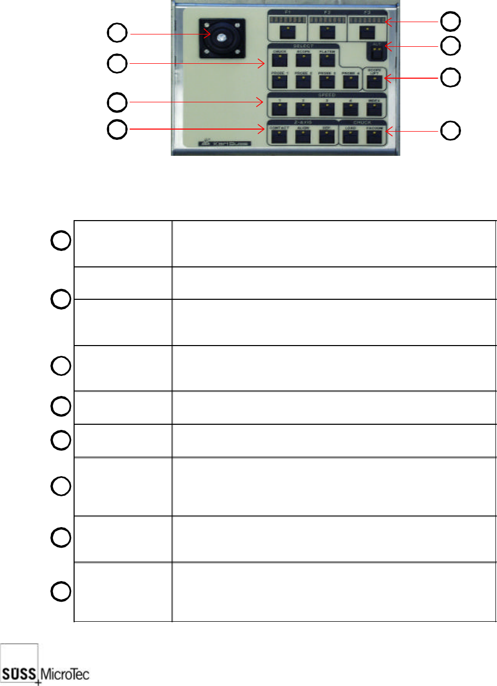
7.3 Joystick Controller
The Joystick Controller provides remote control of all probe system motorized stages
including wafer chuck, microscope, probeheads and platen. The most common
functions, such as load, vacuum, go and set home and contact and two-point alignment
are also provided. It can be used with or without a PC.
Joystick
Used to move motorized stages in the X and Y axes. The joystick
provides proportional control based on the amount of joystick
deflection.
LED Displays (3x)
Indicates the use of the F1-F3 function key below it and updates
each time the Alt key is pressed.
F1-F3 Function
Keys
Used in conjunction with the Alt Key to provide 12 additional
functions. Pressing the key will either carry out the function or
redefine the keys with new functions.
Alt Key
A four-state key as indicated by its LEDs: off-off, off-on, on-off and
on-on. Each press of the Alt key will display the next three functions
in the LED displays.
Lift Key
Raises the microscope to change objectives or facilitate setup. The
LED is lit when the microscope is up.
Select Keys (7x)
Defines the stage to be controlled by the joystick and which stage
the function keys relate to.
Speed Keys (5x)
Sets the speed at which stages move in response to the joystick.
Speed 1: jogs or moves at the smallest stepping increment
Speed 2-4: each cover a speed range (4 = 100%)
Index: moves at a user-defined index value in X or Y direction.
Z-Axis Keys (3x)
Moves the selected stage or probehead to the defined contact, align
and separate positions. Contact must be set by the user before
these keys are operational.
Chuck Keys (2x)
Load lowers the chuck to the lowest or load position, centers in the
X axis and forward towards the user.
Vacuum controls the vacuum to the chuck stage for securing the
wafer or DUT.
1
1
2
3
4
5
6
7
8
2
3
4
8
7
6
5

SUSS / PA300 / User Manual / M10-121841-00 / February 2002
33
7.3.1 Getting Started
This procedure guides the user through a typical set-up, from powering up the system
to aligning theta, setting contact and home, and entering an index.
1. Turn on the power to all components, as detailed in System Power-Up.
2. On the Joystick Controller select the stage to be used: chuck, microscope, platen
or probehead. For this example, the chuck is selected.
3. Select the control speed, typically Speed 4 at a low magnification to locate the
probe tips and target.
4. Press the ALT Key for the Z-axis controls; the right LED is lit. If the chuck is not in
the loading position (front middle), move the chuck there with the joystick. Load
the wafer on the pins and switch on the vacuum. Press Z UP until the wafer is lying
on the chuck in the center.
5. Ensure the platen is in the contact position and raise the chuck, using Z UP and Z
DOWN keys, F2 and F3, so the wafer or DUT is about 1-2 mm from the platen or
probecard. This allows the use of short probe tips and places the wafer within the
working range of probeheads. Press SET CONT, F1 to set contact at this point.
6. Since the chuck will not move while in contact, press Z-Axis Align to lower the
chuck.
7. Use the joystick and microscope focus to get the wafer and probe tips in view. If
equipped with motorized focus Z-axis controls, operate the focus when the
microscope is selected.
8. Press the ALT Key for Align, no are LED’s lit and F3. For a two-point alignment
position the wafer stage near the left (right) edge of the wafer and a horizontal
street or feature is aligned with a crosshair or probe tip reference point. Press
MARK 1. Move to the right (left) edge of the wafer and align with the same street or
feature and press MARK 2. The chuck theta then rotates to correct the rotational
error. Increased magnification and careful alignment increase accuracy. For probing
packaged parts, use the microscope software theta compensation.
9. Position the wafer chuck at the first test point and press SET HOME, Alt Key and
F3.
10. Press Z-Axis Contact to raise the chuck to contact position. Position all probes and
lower to contact.
11. The joystick and Z-Axis controls can now be used to move to more test points. An
index can be set with Alt Key, left LED lit and F3. The F1 and F2 Displays indicate
the index value. Change the index using the joystick and press F1 and F2 to enter.
12. Unloading: With Z DOWN, lower the chuck until it stops. Move chuck to the loading/
unloading position and switch off vacuum (“VAC”). Press Z DOWN until it will not
go further and remove the wafer from the pins.

34
SUSS / PA300 / User Manual / M10-121841-00 / February 2002
7.3.2 F1-F3 Function Keys
Key LEDs F1 F2 F3
Off-off
Off-on
On-off
On-on
ALIGN
SET CONT / SET FOC
REMOTE
IDX POS
GO HOME
Z UP
THETA
REAL POS
SET HOME Z
DOWN
INDEX
QUIET / TURRET
ALIGN redefines the keys as CANCEL, MARK 1 and MARK 2, and starts the 2-point
alignment process.
1. To begin, position the wafer stage near the left (right) edge of the wafer so a
horizontal street or feature is aligned with a crosshair or probe tip reference point
and press MARK 1.
2. Move to the right (left) edge of the wafer and align with the same street or feature
and press MARK 2. The chuck theta will then rotate to correct the rotational error.
Increased magnification and careful alignment increases accuracy.
The same procedure can be used for theta alignment of the microscope and
probeheads. Although the chuck is physically rotated, the microscope and probeheads
are corrected with software. This allows the probehead rotational correction to track
the microscope, so aligning a microscope will automatically align the probeheads.
Packaged parts are easier to align to with the microscope rather than with the chuck.
GO HOME moves the selected stage to the X-Y home position as defined with Set
Home.
SET HOME defines the X-Y home position at the current position and zeros the X-Y
co-ordinates.
SET CONT defines the upper limit of chuck travel, set to provide adequate contact
without device or probe tip damaging excessive overtravel. When set, the function
becomes CL CONT to clear the contact position. The contact position must be set
each time the system is powered-up. The Z-Axis controls of Contact, Align and Separate
cannot be used until contact has been set. When choosing the microscope movement,
SET FOC is displayed – this saves the focus height. With CONTACT it is then moved
into its stored position.
Z UP moves the chosen stage upward at the selected speed.
Z DOWN moves the chosen stage downward at the selected speed.
REMOTE sets a flag to signal a tester the prober is ready, redefines the key as LOCAL
and disables all controls except this button. Pressing LOCAL resets the ready flag and
enables local controls.
THETA redefines the keys as CW, CENTER and CCW and controls the chuck theta in
clockwise, go to center and anticlockwise.
INDEX redefines the keys as X AXIS, Y AXIS and CANCEL. X and CANCEL Y indicate
the index value and may be changed using the joystick. After setting the index, press
the F1 and F2 keys to record. CANCEL exits the procedure.
IDX POS switches the display to show the current position in relation to the home
position in multiples of the set. F1 displays the X distance and F2, the Y value.