SussPA300UserGuide.pdf - 第29页
28 SUSS / PA300 / User Manual / M10-121841-00 / February 2002 6.4 Assembly 6.4.1 Chuck Stage 1. The chuck is secured by a bayonet-type mount that locks and unlocks with a rotating movement. To install, position the four …
SUSS / PA300 / User Manual / M10-121841-00 / February 2002
27
6.3 Mechanical Transport Locks
All movable components of the prober mechanics are secured by transport locks.
These locks must be removed prior to operating the prober.
Note: If the transport locks are not removed prior to operation, this could
result in severe damage.
6.3.1 Platen
The platen is locked in place by four DIN 912 cap screws located at the four corners of
the platen. There are two screws at each corner. One is centered above the column
and secures the platen to the prober; do not remove this screw. The second is offset
from the center of the column and is the transport lock which needs to be removed.
6.3.2 Microscope Movement
The microscope movement transport lock is a bracket located on the right side of
motorized movements. Remove this bracket. A manual movement has 2 brackets, 1
on the front right hand side and 1 on the left front side. They are all clearly marked with
a yellow label.
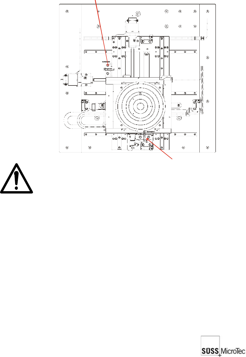
6.3.3 Chuck Stage
The chuck stage is locked by two brackets as illustrated. Remove these brackets. The
stage should now be free to move.
Transport lock for X direction
Transport lock for Y direction

28
SUSS / PA300 / User Manual / M10-121841-00 / February 2002
6.4 Assembly
6.4.1 Chuck Stage
1. The chuck is secured by a bayonet-type mount that locks and unlocks with a rotating
movement. To install, position the four chuck mount pins in the mating holes of the
Z-axis, grasp the chuck at the outer edge and turn clockwise about 20 degrees.
2. Connect the vacuum hose and ground/bias lead to the chuck.
3. Install the stage covers after the system is powered up and the chuck planarity is
checked or adjusted.
6.4.2 Microscope and Movement
1. Mount the microscope (with adapter) to the microscope movement stage using the
four DIN 912 screws provided.
2. If equipped with a motorized focus, the connectors are plugged into the PC-board
under the sheet metal cover at the rear of the movement.
3. Install the objectives, eyepieces, camera adapter and camera on the microscope.
Note that the turret objective port covers are labelled to indicate the correct objective
location. Connect the fiber optic bundle from the microscope illuminator.
6.4.3 Platen
1. Raise the platen approximately 12 mm and push down firmly on all four corners of
the platen to ensure they are properly seated.
2. Lower the platen until it is approximately 2 mm above the full down position.
3. Install the platen height dial indicator on the bracket located on the rear of the
microscope bridge. Secure with the set screw.
4. Operate the contact/separation lever and ensure platen movement of 0.4 mm on
the indicator. If not, reposition the indicator as required.
6.4.4 Non-Electrical Utilities
Connect vacuum and air or nitrogen at the right rear corner of the mechanics.
6.4.5 Open Connections
In order to make safe connections the device must not be connected to the mains.
The probe system can be equipped with a wide range of accessories and options,
each with its own electrical interconnects. All plugs and connectors of SUSS
manufactured equipment are designed to prevent incorrect connections. Exercise extra
care when connecting other components. Generally all plugs and jacks will have number
or function labels to match up. The strapping wires should be mounted properly and
laid so that accidents can be ruled out.
Unused jump cables must not be used for anything else.

SUSS / PA300 / User Manual / M10-121841-00 / February 2002
29
Minimum Connections
These connections are required on a system with no additional options or accessories
(not including power connections):
a. Electronics rack to probe station: Grounding (green/yellow) conductor
b. Electronics rack to mechanic: 3 large cables and connectors, mounted on a common
plate (2 optional).
c. Electronics rack to joystick controller - RS232 standard cable.
d. Electronics rack to computer (PC) - RS232 standard cable.
e. Computer (PC) to monitor, keyboard and mouse (if system is equipped with one).
Please refer to the Ergonomic Information Table in the appendix for more details.
Other Typical Connections
a. Electronics rack to motorized probeheads, edge and contact sensors.
b. Electronics rack to microscope illuminator
c. Camera to computer (PC) or a second monitor.
6.4.6 Electrical Utilities
All components that require AC power input will be labelled with the required input
voltage and VA or wattage.
Please ensure that all power connections are plugged into the correct voltage.
Components that require AC power include:
a. Electronics rack
b. Microscope illuminator
c. Computer (PC) and monitor
d. Camera power supply
Review the Installation Checklist and apply power to all components.
6.4.7 Additional Accessories and Options
All user or operator manuals for additional accessories and options, such as thermal
chuck or laser cutter, are included with the system. Read these manuals for the proper
installation and operation of these components.
6.4.8 System Power-up
Review the Installation Checklist in the appendix and to the Operation chapter for
more information.