SussPA300UserGuide.pdf - 第14页
SUSS / PA300 / User Manual / M10-121841-00 / February 2002 13 3 Facility Requirements and Communication Interface 3.1 Facility Requirements 3.1.1 Environmental Requirements To be used only indoors. Equipment can be used …
12
SUSS / PA300 / User Manual / M10-121841-00 / February 2002
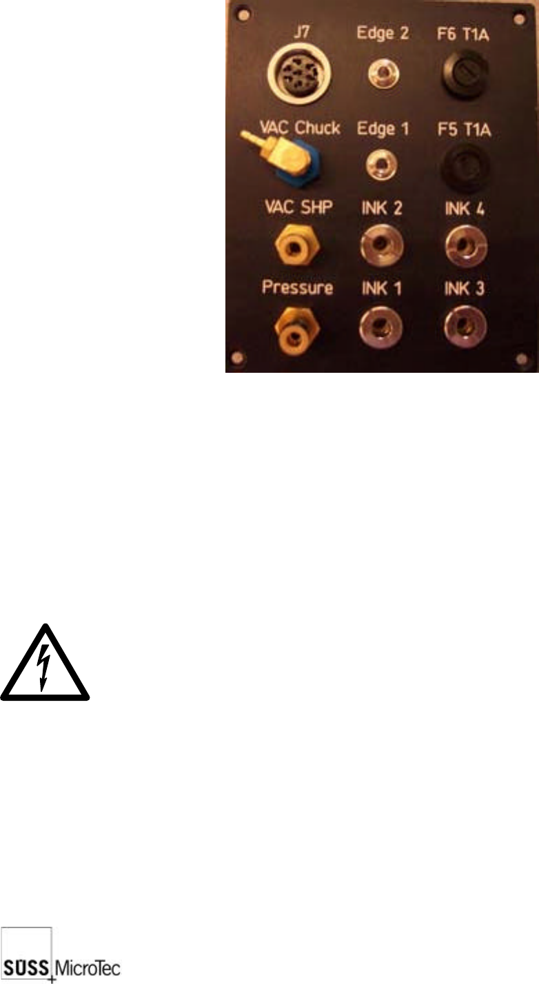
2.11 Utility Distribution
Exits:
VAC CHUCK: Vacuum exit for the chuck
VAC SHP: Vacuum exit for the probe head platen
INK 1...INK4: 4 Inker exits (each roughly 24V)
J7: Optional 24V or 5V power supply
Entrances:
EDGE 1...2: 2 Edge sensors
INK and EDGE leads are low voltage. For safety reasons, the low voltage leads
should be isolated. These should not be touched during operation.
SUSS / PA300 / User Manual / M10-121841-00 / February 2002
13
3 Facility Requirements and Communication
Interface
3.1 Facility Requirements
3.1.1 Environmental Requirements
To be used only indoors. Equipment can be used up to a height of 2000m above sea
level. In order for the prober to work to its optimum potential, the environmental
temperature must be between 5°C and 40°C by a maximum humidity of 80%. With
temperatures up to 31°C and above that linearly decreasing to 50% at 40°C.
The probe system is located on a vibration isolation table, which is delivered with the
PA300 system. This table makes a mechanical unit together with the basic prober
equipment. As this equipment has brackets and other mechanisms to secure for
earthquake protection, drifting will not occur. The area must be maintained at room
temperature between 19°C and 24°C with a relative humidity of 40-60% in order for
the system to work accurately. The area must be clean as the PA300 has been designed
only for use in clean rooms and laboratories.
Since the probe system as well as the devices under test could be affected by static
electricity, the system should be installed in an area where the floor covering does not
generate a static charge, or so the static can be discharged through static mats, wrist
straps, or similar methods.
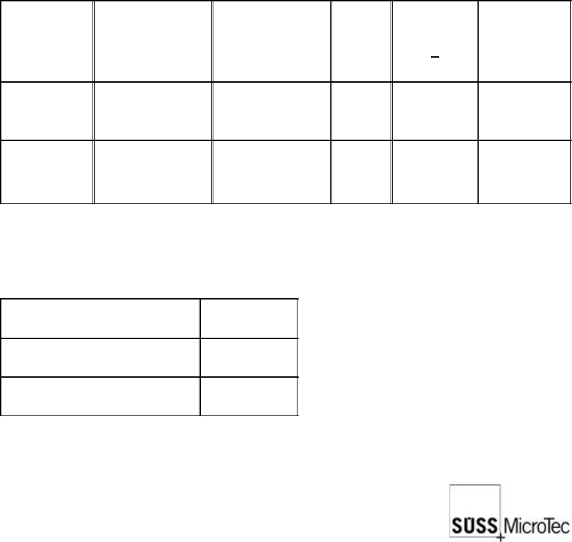
Temperature
Operating
Range
min./max: (°C)
Optimal
Operating
Range
min./max. (°C)
Target
Temp.
(°C)
Tolerance
+
Max. Rate
of Change
/Hour
Tool Area
5 - 40 °C 19 - 24 °C 22 °C 1K
Not
specified
Support
Equipment
Area
5 - 40 °C 19 - 24 °C 22 °C 1K
Not
specified
Relative Humidity
Range (%)
Tool Area 40 to 60
Support Equipment Area
40 to 60
14
SUSS / PA300 / User Manual / M10-121841-00 / February 2002
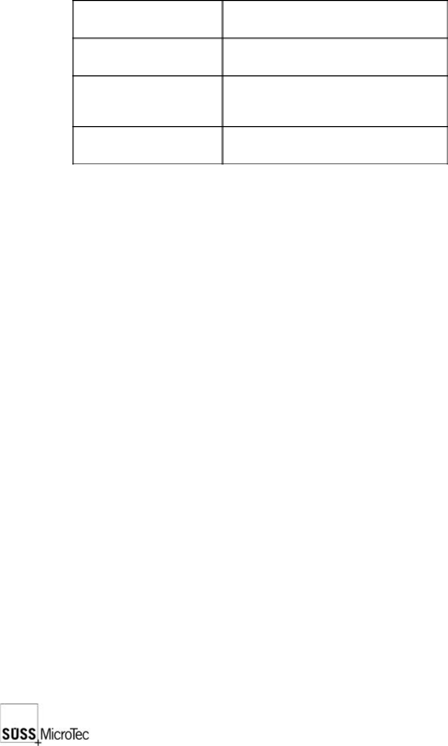
3.1.2 Noise Level
Measured equipment
PA300, standard
Experiment conditions,
equipment
Mechanical stage, standard
Measuring conditions,
measuring device
Noise level measuring device SL4001/2
Accuracy class 3
Measured in operating position
Results
Constant level: 56 dB (A)
Impulse: 72 dB (A)
3.1.3 RF Frequencies, Electrostatic Discharge and Non-Ionizing
Radiation
This equipment does not produce dangerous electromagnetic radiation, electromagnetic
interference, radio frequency, acoustical vibrations or electrostatic discharge.
The PA300 system is class A equipment and is designed for use in industry.
It can in non-industrial areas, however, cause radio interference but there is no need to
act on it. During normal operation the rays create no special risks. Disturbances can
be a positional problem. If this does occur, it is expected that the customer will carry
out any suitable measures and bare the cost.
Interference to the video system screen through electromagnetic radiation does not
influence the movement of the mechanical stage. During operation or service the user
should avoid touching unearthed contacts. In equipment operation or service it is the
user’s responsibility to unload unearthed parts.
3.2 Vibration Requirements and Earthquake Protection
This equipment does not produce vibrations. In case of vibration sensitivity, however,
it is suggested that the PA300 is set on a vibration isolation table in order that the
equipment is not disturbed by movement from outside i.e.: earthquakes or tremors.
3.3 Media Requirements
3.3.1 Vacuum
Less than 200 mbar absolute, flow rate insignificant. Vacuum inputs ¼” or 6mm. All
connections to house vacuum system should be separate to avoid vacuum interference.
System Input
U.S. installations are 1/4“ hose, international installations are 6 mm.