4OM-1054-002.pdf - 第69页
(3) Checking of Attached V acuum Nozzle • After the vacuum nozzle is attached, rotate the rotary turret with the cam hand-rotating wheel to let the nozzle pass over the dropped nozzle detection plate. Check that the end …
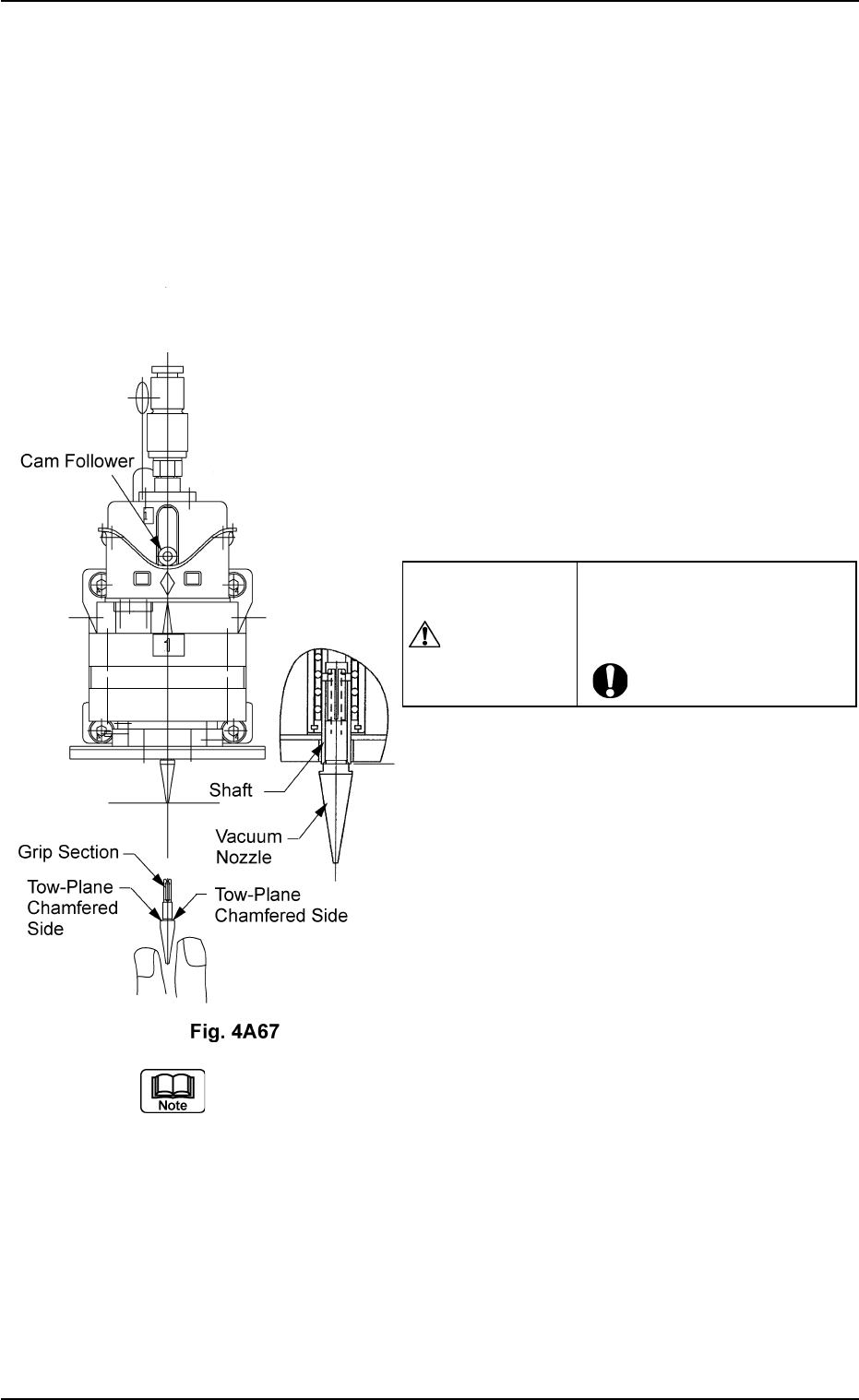
(2) Attachment of Vacuum Nozzle
• Before attaching a vacuum nozzle, check that the end of the nozzle
is not damaged, the tapered section is unscratched, the pick-up hole
unclogged, and the grip section undeformed.
• Select the nozzle which meets the parameters specified in the place-
ment head nozzle data.
(2-1) Move the center shaft of the nozzle position
No. to be attached toward the front side of
the machine.
(2-2) While holding the cam follower with your fin-
ger, orient the two-plane chamfered side
horizontally and insert the vacuum nozzle
over the shaft until it stops.
(2-3) Set the [OPERATION] switch to the "RUN"
side.
(2-4) Use the "Head/Nozzle" tab in the "TEACH-
ING" window (submenu) and perform a
teaching operation on the nozzle.
Do not scratch the diffusion plate while attaching a vacuum nozzle.
0211-004 1-54
AGS01ETRP
1.4 Maintenance Method
CAUTION
Inserting a nozzle forcibly
over the shaft in wrong direc-
tion deforms the grip section.
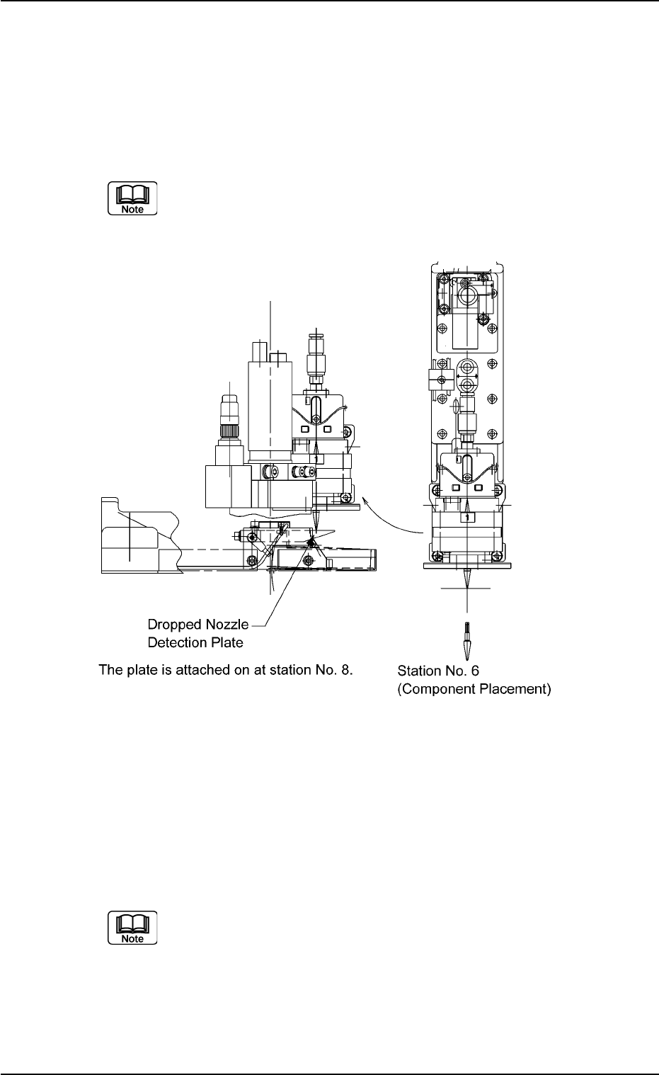
(3) Checking of Attached Vacuum Nozzle
• After the vacuum nozzle is attached, rotate the rotary turret with the
cam hand-rotating wheel to let the nozzle pass over the dropped nozzle
detection plate. Check that the end of the nozzle does not touch the
plate. If it touches the plate, re-attach the vacuum nozzle.
The vacuum nozzle should be set in the descending mode
when it passes over the dropped nozzle detection plate.
Fig. 4A68
(4) Nozzle Offset Teaching
Refer to "5.4 "Head/Nozzle" Tab" in "Section 6" of "Volume 2: Opera-
tion (Supervisor)" for details and perform teaching operations.
Wipe off dirt and dust on the end of a nozzle which was detected as
defective through teaching operation and then re-perform the teaching
operation.
Refer to "5.4 "Head/Nozzle" Tab" in "Section 6" of "Volume 2:
Operation (Supervisor)" for the items to be checked when a
nozzle is detected as a defective one through teaching opera-
tion.
When the machine operation is started with a defective
nozzle (detected by teaching operation) attached, the nozzle
is bypassed and not used.
0211-004 1-55
AGS01ETRP
1.4 Maintenance Method
1.4.5 Disassembly, Cleaning, and Lubrication of Miniature Stroke
Bearing
Since the disassembly, cleaning, and lubrication work
of the miniature stroke bearings requires highly so-
phisticated technique, consult our service personnel
for details.
••
••
• Time for Inspection, Cleaning, and Lubrication
Perform inspections every month.
Cleaning and lubrication are required when dirt and dust have accu-
mulated on the sliding part of the shaft and the movement is ham-
pered or on the hollow portion of the shaft and the suction force has
deteriorated.
Be sure to clean the miniature stroke bearing every 6 months.
••
••
• Disassembly of Miniature Stroke Bearing
Disassembly Procedure
(1) Set all nozzles to "L Level".
Refer to "4.2.2 "Mnl Opn Menu" Tab" in "Sec-
tion 6 (Volume 2: Operation (Supervisor))" for
the detailed information on how to change the
nozzle level.
(2) Make the X/Y table escape.
Refer to "4.2.1 "Noz Cleaning" Tab" in "Sec-
tion 6 (Volume 2: Operation (Supervisor))" for
the detailed information on how to make the
X/Y table escape.
(3) Turn off the power and air sources of the ma-
chine to discharge the air from the machine.
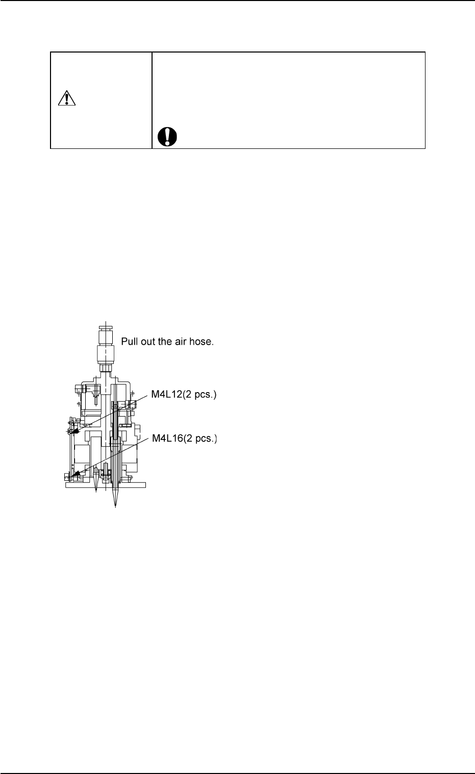
(4) Detachment of Head Assembly
(4-1) Loosen 2 M4L12 bolts (upper ones) and 2
M4L16 bolts (lower ones) fastening the head
and detach the head assembly.
(4-2) Pull out the air hose.
(4-3) Pull the head forward to detach.
Fig. 4A69
0303-005 1-56
AGS01ETRP
1.4 Maintenance Method
CAUTION