4OM-1054-002.pdf - 第80页
• Return the lever to the original position. • Put a new lamp in the lamp socket and push it down until it reaches the bottom of the lamp holder . At this time, direct the side of the lamp where the projected section is …
1.4.6 Lamp Replacement of Light Source Device for Recognition
Lighting
(1) Light Source Devices
Light Source Devices : #MHF-P100LRD-SO-2
Lamp : LM-100
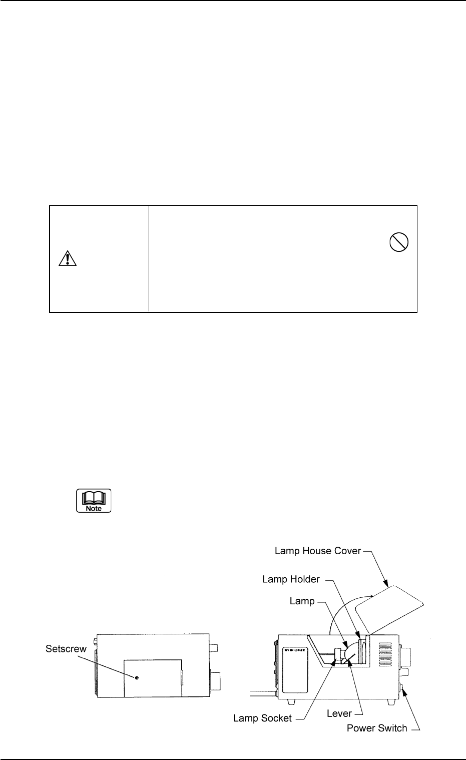
(2) Lamp Replacement Procedure
• Turn off the power switch of the light source device and check that
the LED (Orange) of the power switch extinguishes.
• Loosen the setscrew on the main body of the light source device and
open the lamp house cover.
• Lift the lever located on the left side of the lamp in the arrow direction.
The lamp will also be lifted up.
• Pull out the lamp straight up from the lamp holder.
• Detach the lamp from the socket.
When the lamp is inserted or pulled out, be sure not to forcibly
screw the terminal into or unscrew it from the socket. Other-
wise, the socket may be damaged.
Fig. 4A83
Do not touch the lamp right after it has been turned
off because it is very hot. Wait for until it cools
down.
Be sure to wear gloves made of thick
material (for example, cotton work gloves) to replace
the lamp right after it has been turned off.
CAUTION
0307-005 1-64 AGS01ETRP
1.4 Maintenance Method
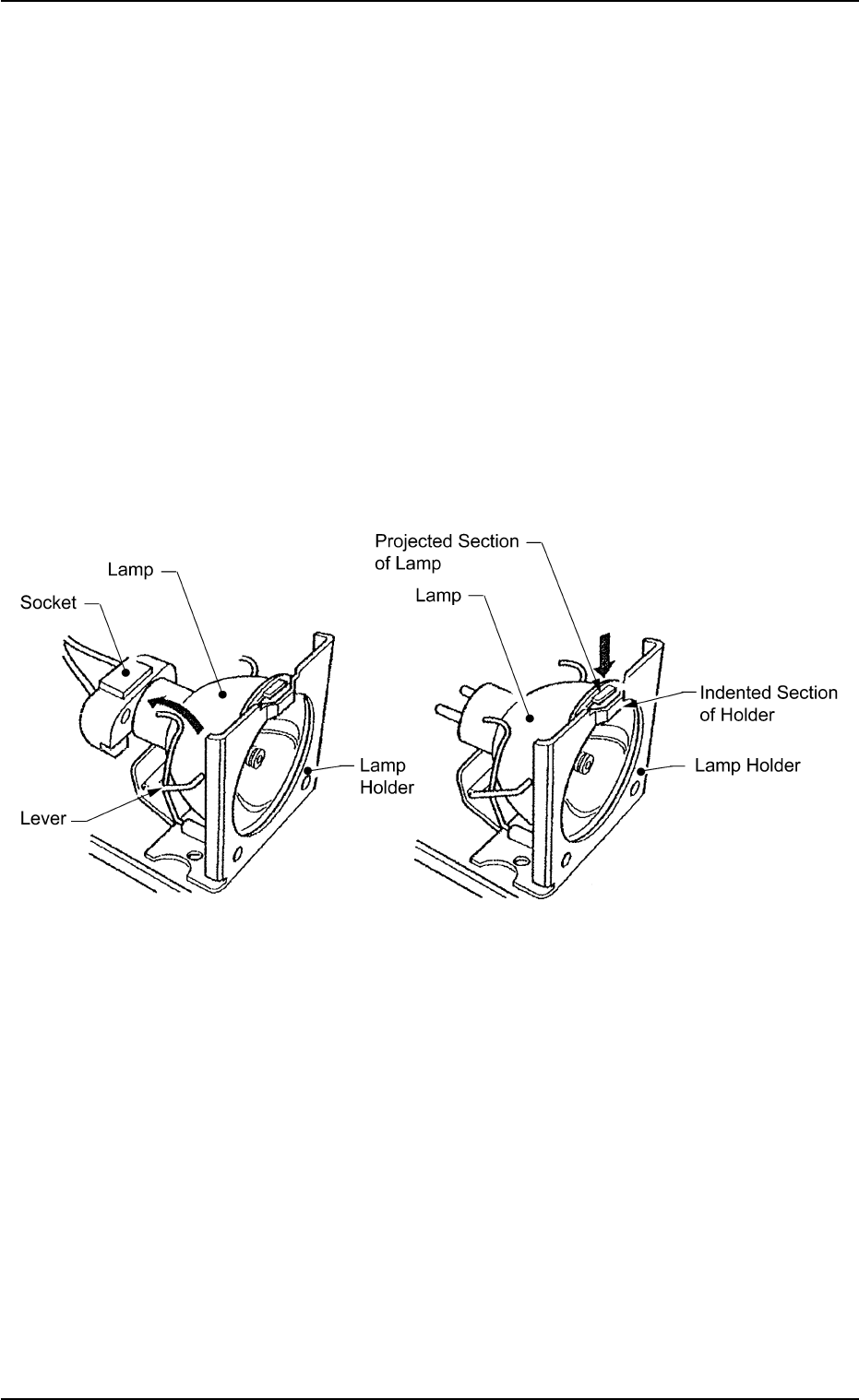
• Return the lever to the original position.
• Put a new lamp in the lamp socket and push it down until it reaches
the bottom of the lamp holder. At this time, direct the side of the lamp
where the projected section is located so that the projection matches
the indented section of the lamp holder.
• Close the lamp house cover and shift down the lock lever to fasten
the cover.
• Turn on the power switch of the light source device and check that
the LED (orange) of the power switch illuminates.
• The lamp replacement is completed.
Perform lighting check operation after lamp replacement.
Fig. 4A84
0211-004 1-65 AGS01ETRP
1.4 Maintenance Method
0303-005 1-66 AGS01ETRP
1.4 Maintenance Method
1.4.7 Replacement of Cutter Blade
Time of Replacement
Replace a cutter blade with a new one when the cutting quality has
deteriorated due to wear, cracks, etc.
Replacement Procedure
(1) Zero the feeder carriage and turn off the power supply.
(2) Open the central safety guard of the feeder unit.
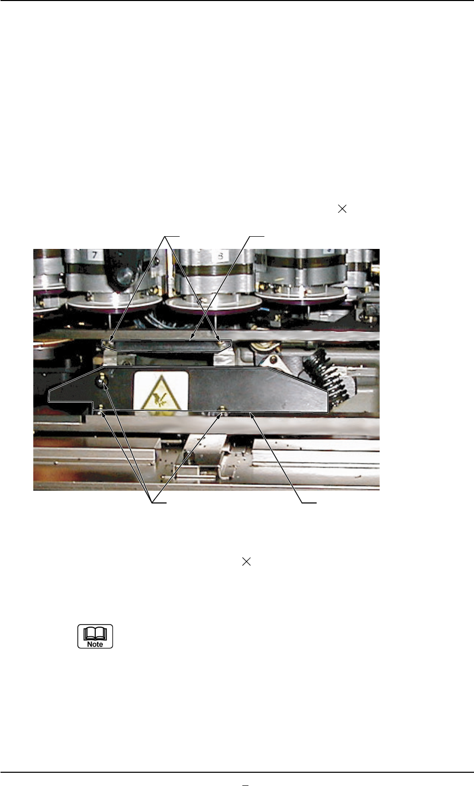
(3) Detach the upper blade by removing Bolts A (M5 16).
Fig. 4A84-1
(4) Remove SEMS-BOLT B (M5 12) fastening the lower blade hold-
ing plate with the torque L-type wrench (Standard Accessory Part:
630 063 9759) and detach the plate.
While detaching the lower blade holding plate, be careful not
to touch the nozzles and diffusion plates. Also, avoid hitting
them with a tool.
Upper Blade
Lower Blade Holding Plate
Bolts A
Bolts B