IPC-SM-782A-表面贴装焊盘图形设计标准.pdf.pdf - 第159页
RLP No. Component Identifier Z (mm) G (mm) X (mm) Y (mm) C (mm) D (mm) E (mm) Placement Grid (No. of Grid Elements) ref ref ref ref 630A QFP 32x32-184 35.80 32.20 0.40 1.80 34.00 29.25 0.65 74x74 631A SQFP 32x32-240 34.80…
Component
Identifier
L (mm) S (mm) W (mm) T (mm)
A
(mm)
B
(mm)
P
(mm)
H
(mm)
min max min max min max min max ref ref basic max
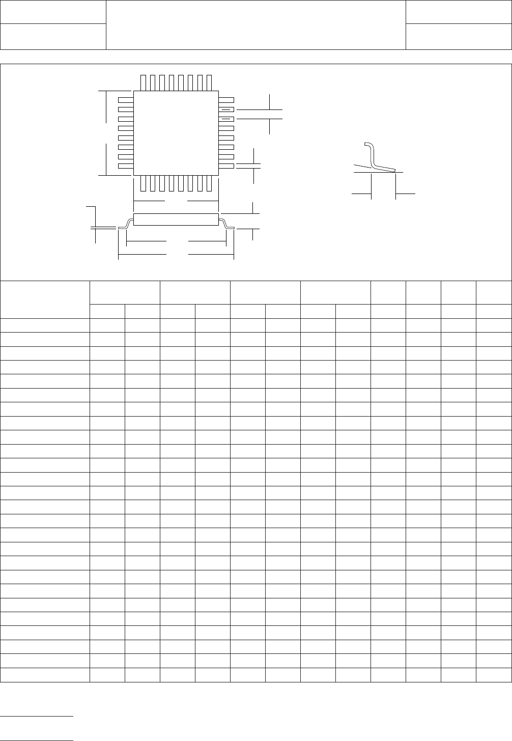
QFP 32x32-184 34.95 35.45 33.05 33.71 0.22 0.38 0.65 0.95 32.00 32.00 0.65 4.20
SQFP 32x32-240 33.80 34.20 32.20 32.89 0.10 0.30 0.40 0.80 32.00 32.00 0.50 4.20
SQFP 32x32-248 33.80 34.20 32.20 32.89 0.10 0.30 0.40 0.80 32.00 32.00 0.50 4.20
SQFP 32x32-304 33.80 34.20 32.20 32.89 0.05 0.22 0.40 0.80 32.00 32.00 0.40 4.20
SQFP 32x32-312 33.80 34.20 32.20 32.89 0.05 0.22 0.40 0.80 32.00 32.00 0.40 4.20
SQFP 32x32-400 33.80 34.20 32.20 32.89 0.05 0.15 0.40 0.80 32.00 32.00 0.30 4.20
SQFP 32x32-408 33.80 34.20 32.20 32.89 0.05 0.15 0.40 0.80 32.00 32.00 0.30 4.20
SQFP 36x36-272 37.80 38.20 36.20 36.89 0.10 0.30 0.40 0.80 36.00 36.00 0.50 4.20
SQFP 36x36-280 37.80 38.20 36.20 36.89 0.10 0.30 0.40 0.80 36.00 36.00 0.50 4.20
SQFP 36x36-344 37.80 38.20 36.20 36.89 0.05 0.22 0.40 0.80 36.00 36.00 0.40 4.20
SQFP 36x36-352 37.80 38.20 36.20 36.89 0.05 0.22 0.40 0.80 36.00 36.00 0.40 4.20
SQFP 36x36-456 37.80 38.20 36.20 36.89 0.05 0.15 0.40 0.80 36.00 36.00 0.30 4.20
SQFP 36x36-464 37.80 38.20 36.20 36.89 0.05 0.15 0.40 0.80 36.00 36.00 0.30 4.20
QFP 40x40-232 42.95 43.45 41.05 41.71 0.22 0.38 0.65 0.95 40.00 40.00 0.65 4.20
SQFP 40x40-304 41.80 42.20 40.20 40.89 0.10 0.30 0.40 0.80 40.00 40.00 0.50 4.20
SQFP 40x40-312 41.80 42.20 40.20 40.89 0.10 0.30 0.40 0.80 40.00 40.00 0.50 4.20
SQFP 40x40-384 41.80 42.20 40.20 40.89 0.05 0.22 0.40 0.80 40.00 40.00 0.40 4.20
SQFP 40x40-392 41.80 42.20 40.20 40.89 0.05 0.22 0.40 0.80 40.00 40.00 0.40 4.20
SQFP 40x40-512 41.80 42.20 40.20 40.89 0.05 0.15 0.40 0.80 40.00 40.00 0.30 4.20
SQFP 40x40-520 41.80 42.20 40.20 40.89 0.05 0.15 0.40 0.80 40.00 40.00 0.30 4.20
SQFP 44x44-336 45.80 46.20 44.20 44.89 0.10 0.30 0.40 0.80 44.00 44.00 0.50 4.20
SQFP 44x44-344 45.80 46.20 44.20 44.89 0.10 0.30 0.40 0.80 44.00 44.00 0.50 4.20
SQFP 44x44-424 45.80 46.20 44.20 44.89 0.05 0.22 0.40 0.80 44.00 44.00 0.40 4.20
SQFP 44x44-432 45.80 46.20 44.20 44.89 0.05 0.22 0.40 0.80 44.00 44.00 0.40 4.20
SQFP 44x44-568 45.80 46.20 44.20 44.89 0.05 0.15 0.40 0.80 44.00 44.00 0.30 4.20
SQFP 44x44- 576 45.80 46.20 44.20 44.89 0.05 0.15 0.40 0.80 44.00 44.00 0.30 4.20
Figure 2d SQFP/QFP (square) component dimensions
S
L
0~ 0.25
B
A
W
P
▼
▼
▼
▼
▼
▼
▼
▼
▼
▼
▼
▼
▼
▼
0~ 10°
T
▼
▼
▼
▼
H
IPC-782-11-2-2d
IPC-SM-782
Subject
SQFP/QFP (Square)
Date
5/96
Section
11.2
Revision
A
Page8of10
RLP No. Component Identifier Z (mm) G (mm) X (mm)
Y (mm) C (mm) D (mm) E (mm)
Placement Grid
(No. of Grid
Elements)ref ref ref ref
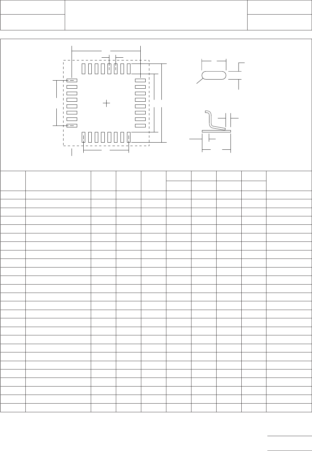
630A QFP 32x32-184 35.80 32.20 0.40 1.80 34.00 29.25 0.65 74x74
631A SQFP 32x32-240 34.80 31.60 0.30 1.60 33.20 29.50 0.50 72x72
632A SQFP 32x32-248 34.80 31.60 0.30 1.60 33.20 30.50 0.50 72x72
633A SQFP 32x32-304 34.80 31.60 0.25 1.60 33.20 30.00 0.40 72x72
634A SQFP 32x32-312 34.80 31.60 0.25 1.60 33.20 30.80 0.40 72x72
635A SQFP 32x32-400 34.80 31.60 0.17 1.60 33.20 29.70 0.30 72x72
636A SQFP 32x32-408 34.80 35.60 0.17 1.60 33.20 30.30 0.30 72x72
640A SQFP 36x36-272 38.80 35.60 0.30 1.60 37.20 33.50 0.50 80x80
641A SQFP 36x36-280 38.80 35.60 0.30 1.60 37.20 34.50 0.50 80x80
642A SQFP 36x36-344 38.80 35.60 0.25 1.60 37.20 34.00 0.40 80x80
643A SQFP 36x36-352 38.80 35.60 0.25 1.60 37.20 34.80 0.40 80x80
644A SQFP 36x36-456 38.80 35.60 0.17 1.60 37.20 33.90 0.30 80x80
645A SQFP 36x36-464 38.80 35.60 0.17 1.60 37.20 34.50 0.30 80x80
650A QFP 40x40-232 43.80 40.20 0.40 1.80 42.00 37.05 0.65 90x90
651A SQFP 40x40-304 42.80 39.60 0.30 1.60 41.20 37.50 0.50 88x88
652A SQFP 40x40-312 42.80 39.60 0.30 1.60 41.20 38.50 0.50 88x88
653A SQFP 40x40-384 42.80 39.60 0.25 1.60 41.20 38.00 0.40 88x88
654A SQFP 40x40-392 42.80 39.60 0.25 1.60 41.20 38.80 0.40 88x88
655A SQFP 40x40-512 42.80 39.60 0.17 1.60 41.20 38.10 0.30 88x88
656A SQFP 40x40-520 42.80 39.60 0.17 1.60 41.20 38.70 0.30 88x88
660A SQFP 44x44-336 46.80 43.60 0.30 1.60 45.20 41.50 0.50 96x96
661A SQFP 44x44-344 46.80 43.60 0.30 1.60 45.20 42.50 0.50 96x96
662A SQFP 44x44-424 46.80 43.60 0.25 1.60 45.20 42.00 0.40 96x96
663A SQFP 44x44-432 46.80 43.60 0.25 1.60 45.20 42.80 0.40 96x96
664A SQFP 44x44-568 46.80 43.60 0.17 1.60 45.20 42.30 0.30 96x96
665A SQFP 44x44-576 46.80 43.60 0.17 1.60 45.20 42.90 0.30 96x96
Figure 3d SQFP/QFP (square) land pattern dimensions
Y
X
Full radius
optional
▼
▼
▼
▼
▼
▼
▼
▼
▼
▼
▼
E
▼
▼
C
▼
▼
GZ
▼
▼
▼
▼
Grid placement courtyard
▼
D
▼
▼
D
▼
▼
IPC-782-11-2-3d
IPC-SM-782
Subject
SQFP/QFP (Square)
Date
5/96
Section
11.2
Revision
A
Page9of10
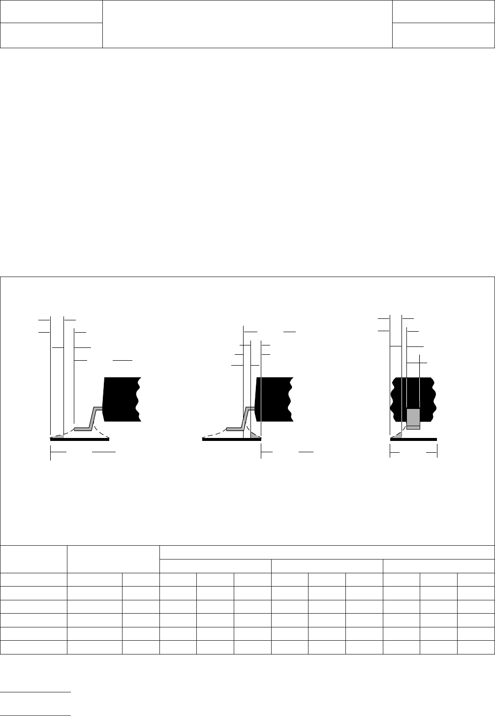
6.0 TOLERANCE AND SOLDER JOINT ANALYSIS
Figure 4 provides an analysis of tolerance assumptions and
resultant solder joints based on the land pattern dimensions
shown in Figure 3. Tolerances for the component dimensions,
the land pattern dimensions (fabrication tolerances on the
interconnecting substrate), and the component placement
equipment accuracy are all taken into consideration.
Figure 4 provides the solder joint minimums for toe, heel, and
side fillets, as discussed in Section 3.3. The tolerances are
addressed in a statistical mode, and assume even distribution
of the tolerances for component, fabrication, and placement
accuracy.
Individual tolerances for fabrication (‘‘F’’) and component
placement equipment accuracy (‘‘P’’) are assumed to be as
given in the table. These numbers may be modified based on
user equipment capability or fabrication criteria. Component
tolerance ranges (C
L
,C
S
, and C
W
) are derived by subtracting
minimum from maximum dimensions given in Figure 2. The
user may also modify these numbers, based on experience
with their suppliers. Modification of tolerances may result in
alternate land patterns (patterns with dimensions other than
the IPC registered land pattern dimensions).
The dimensions for minimum solder fillets at the toe, heel, or
side (J
T
,J
H
,J
S
) have been determined based on industry
empirical knowledge and reliability testing. Solder joint
strength is greatly determined by solder volume. An observ-
able solder fillet is necessary for evidence of proper wetting.
Thus, the values in the table usually provide for a positive sol-
der fillet. Nevertheless, the user may increase or decrease the
minimum value based on process capability.
Component
Pitch (mm)
Tolerance
Assumptions (mm)
Solder Joint
Toe (mm) Heel (mm) Side (mm)
Basic F P C
L
J
T
min J
T
max C
S
J
H
min J
H
max C
w
J
S
min J
S
max
0.80 0.10 0.10 0.50 0.17 0.43 0.66 0.42 0.75 0.15 0.00 0.10
0.65 0.10 0.10 0.50 0.17 0.43 0.66 0.42 0.75 0.16 –0.02 0.09
0.50 0.10 0.10 0.50 0.29 0.50 0.69 0.29 0.65 0.20 –0.02 0.10
0.40 0.10 0.10 0.50 0.29 0.50 0.69 0.29 0.65 0.17 –0.01 0.10
0.30 0.10 0.10 0.50 0.29 0.50 0.69 0.29 0.65 0.10 –0.03 0.06
Figure 4 Tolerance and solder joint analysis
Zmax
Lmin
▼
▼
▼
▼
1
/2 T
T
J
T
min
Zmax = Lmin + 2J
T
min + T
T
Where:
J
T
min = Minimum toe fillet
T
T
= Combined tolerances
at toe fillet
Smax
J
H
min
Gmin = Smax - 2J
H
min - T
H
Where:
J
H
min = Minimum heel fillet
T
H
= Combined tolerances
at heel fillet
1
/2 T
H
Xmax
Xmax = Wmin + 2J
S
min + T
S
Where:
J
S
min = Minimum side fillet
T
S
= Combined tolerances
at side fillet
▼
▼
Toe Fillet
▼
▼
▼
Heel Fillet Side Fillet
▼
▼
▼
▼
▼
J
T
max
J
H
max
J
S
min
▼
▼
▼
▼
▼
▼
▼
▼
▼
▼
▼
▼
▼
▼
▼
Gmin
▼
1
/2 T
S
J
S
max
▼
▼
▼
Wmin
▼
IPC-782-11-2-4
IPC-SM-782
Subject
SQFP/QFP (Square)
Date
5/96
Section
11.2
Revision
A
Page 10 of 10