IPC-SM-782A-表面贴装焊盘图形设计标准.pdf.pdf - 第62页
In-line placement equipment (Figure 7–4) employs a series of fixed position placement stations. Each station places its respective component as the printed board moves down the line. Cycle times vary from 1.8 to 4.5 secon…

7.0 ASSEMBLY CONSIDERATIONS FOR SURFACE
MOUNT TECHNOLOGY (SMT)
The smaller size of surface mount components and the
option of mounting them on either or both sides of the
packaging and interconnecting structure reduces board real
estate significantly. The type of SMT assembly is basically
determined by the type of surface mount components to be
used; see paragraph 3.6.1.5 for a description of types and
classes.
This section will briefly discuss the assembly process
issues for SMT assemblies. For additional information, see
IPC-SM-780 and IPC-CM-770. The reader is also directed
to IPC-9191 for continued process improvement.
7.1 SMT Assembly Process Sequence The SMT assem-
blies are soldered by reflow (vapor phase, infra red, hot air,
convection, laser, conduction belt) and/or wave soldering
processes depending upon the mix of surface mount and
through hole mount components.
The process sequence for Type 2c SMT is shown in Figure
7–1. The leaded components are automatically or hand
inserted. The assembly is turned over and adhesive applied.
Then the surface mount components are placed by a pick-
and-place machine, the adhesive is cured, the assembly is
turned over again and the wave soldering process is used to
solder both leaded and surface mount components in a
single operation. Finally the assembly is cleaned,
inspected, repaired if necessary, and tested.
The process sequence for Type 1b SMT is shown in Figure
7–2. Solder paste is applied, components are placed, the
assembly is reflow soldered and cleaned. For Type 2b SMT
assemblies, the board is turned over and the process
sequence just described is repeated.
The process sequence for Type 2c Complex SMT, shown in
Figure 7–3, is simply a combination of SMT processes.
7.2 Substrate Preparation Adhesive, Solder Paste
7.2.1 Adhesive Application
In wave soldering of SMT,
selection and application of adhesive plays a critical role.
With too much adhesive, the adhesive gets on lands result-
ing in poor solder fillets. Too little adhesive will fail to
accomplish its objective of holding parts to the bottom of
the board during wave soldering.
A good adhesive has desirable properties such as being
single part, colored, long shelf life, ease of application, and
an adequate bond strength with short cure time. In addition,
after curing and soldering, the adhesive should remain
moisture resistant, nonconductive, noncorrosive, and be
reworkable. There are various companies that supply adhe-
sives for SMT. Some of these adhesives require UV cure
followed by IR; others can be cured in IR (infrared) or
conventional ovens.
For adhesive cure, temperature plays a bigger role than the
time. Only 10°C temperature variation from the recom-
mended cure temperature may cause loss of chips in the
wave (under cure) or difficult repair problems (overcure).
7.2.2 Conductive Epoxy Some applications for SMT
attachment use conductive epoxy as the attachment mate-
rial. Adequate conductive epoxy volume is essential at the
location of the epoxy on the land.
Unlike solder paste which is redistributed when reflowed,
conductive epoxies must be properly controlled to ensure
adequate joint strength. Also, component placement must
be controlled in order to prevent epoxy squeeze-out, and
possible shorts to adjacent lands.
7.2.3 Solder Application, Paste, and Preform Solder
paste plays an important role in reflow soldering. The paste
acts as an adhesive before reflow. It contains flux, solvent,
suspending agent, and alloy of the desired composition. In
selecting a particular paste, rheological characteristics such
as viscosity, dispensing, screening or stencil, flow, and
spread are very important. Susceptibility of the paste to
solder ball formation and wetting characteristics are also
important.
Solder paste is applied on the lands before component
placement either by screening, stenciling, or syringe.
Screens are made from stainless steel or polyester wire
mesh and stencils are etched stainless steel, brass sheets
and other stable alloy
Stencils are preferred for high volume applications. They
are more durable than screens, easier to align, and can be
used to apply a thicker layer of solder paste.
Solder preforms are sometimes used for through-board-
mounted devices. They come in required size and compo-
sition, with flux either inside the preforms, or as a coating
or without flux. They may be cost effective to avoid wave
solder processes if there are only a few leaded components
on the board.
7.2.4 Solid Solder Deposition
7.3 Component Placement
The accuracy requirements
almost make it mandatory to use autoplacement machines
for placing surface mount components on the board. Selec-
tion of the appropriate autoplacement machine is dictated
by the type of parts to be placed and their volume. There
are basically four types of autoplacement machines
available.
• In-line placement
• Simultaneous placement
• Sequential placement
• Sequential/simultaneous placement
December 1999 IPC-SM-782A
53
In-line placement equipment (Figure 7–4) employs a series
of fixed position placement stations. Each station places its
respective component as the printed board moves down the
line. Cycle times vary from 1.8 to 4.5 seconds per board.
Simultaneous placement equipment (Figure 7–5) places an
entire array of components on the printed board at the same
time. Typical cycle times vary from 7 to 10 seconds per
board.
IPC-782-7-1
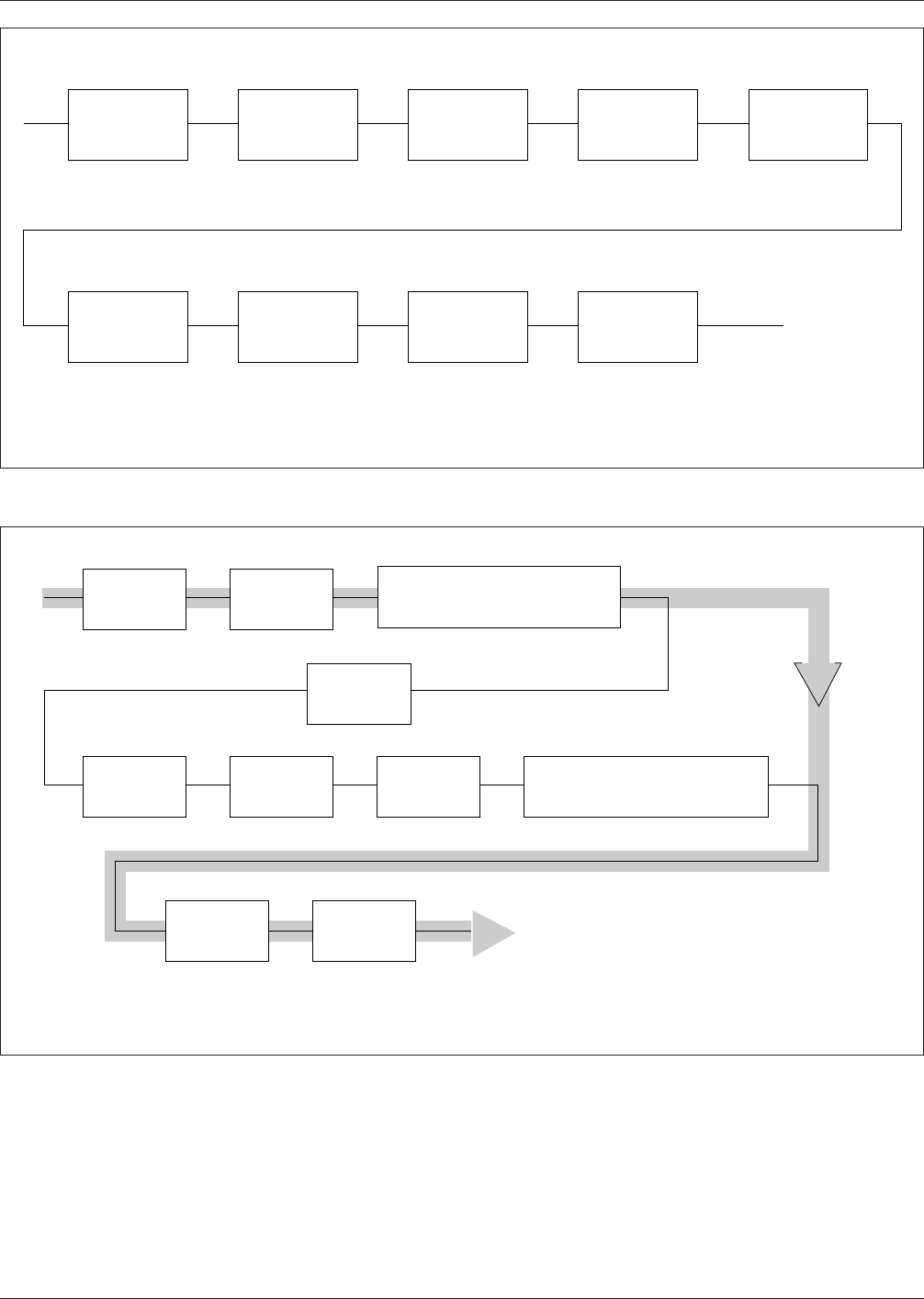
Figure 7–1 Typical process flow for underside attachment type 2c (simple) surface mount technology
Insert/Clinch
Leaded
Thru-Hole
Components
▼
▼
▼
Invert
Board
▼
▼
▼
▼
▼
▼
▼
▼
▼
▼
Apply
Adhesive
Cure
Adhesive
Place
Surface Mt.
Components
Invert
Board
Wave
Solder
Clean*
Test
▼
*Optional depending on flux and cleanliness requirements.
IPC-782-7-2
Figure 7–2 Typical process flow for full surface mount type 1b and 2b surface mount technology
Print
Solder Paste
Side 1
▼
▼
Place
Components
▼
▼
▼
▼
▼
▼
▼
▼
Clean*
Invert
Board
Clean*
Type 2 (Double Sided) SMT
Type 1 (Single Sided) SMT
▼
Print
Solder Paste
Side 2
Place
Components
Dry
Paste**
Test
Reflow
Solder
*Optional depending on flux
and cleanliness requirements
**Typically used for vapor phase soldering
Dry
Paste**
Reflow
Solder
IPC-SM-782A December 1999
54
Sequential placement equipment (Figure 7–6) typically uti-
lizes a software controlled X-Y moving table system. Com-
ponents are individually placed on the printed board in
succession. Typical cycle times vary from 0.3 to 1.8 sec-
onds per component.
Sequential/simultaneous placement equipment (Figure 7–7)
features a software controlled X-Y moving table system.
Components are individually placed on the printed board
from multiple heads in succession. Simultaneous firing of
heads is possible. Typical cycle times vary around 0.2 sec-
onds per component.
There are many autoplacement machines available in each
of the four categories. One must establish guidelines for
selection of a machine. For example, what kind of parts are
to be handled? Will they come in bulk, magazine, or on a
tape? Can the machine accommodate future changes in
tape sizes?
Selection and evaluation of tapes from various vendors for
compatibility with the selected machine is very important.
The off-line programming, teach mode, and edit capability
along with computer aided design/computer aided manu-
facture (CAD/CAM) compatibility may be very desirable,
especially if a company has already developed a CAD/
CAM data base. Special features such as adhesive applica-
tion, component testing, board handling, and reserve capa-
bility for further expansion in a machine may be of special
interest for many applications. Reliability, accuracy of
placement, and easy maintenance are important to all users.
IPC-782-7-3
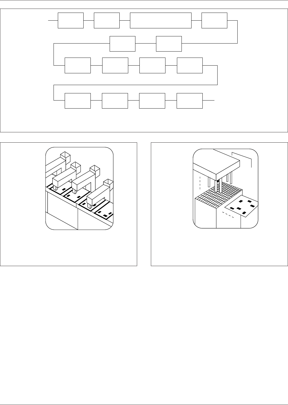
Figure 7–3 Typical process flow for mixed technology type 2c (complex) surface mount technology
''' '
''''
'''' '
'''
'
'
Print
Solder Paste
Dry
Paste**
Reflow
Solder
Place
Surface Mt.
Components
Clean*
Clinch Leaded
Thru-Hole
Components
Insert
Thru-Hole
Components
Invert
Board
Invert
Board
Wave
Solder
Apply
Adhesive
Cure
Adhesive
Place
Surface Mt.
Components
Clean* Test
*Optional depending on flux and cleanliness requirements. If no flux is used for solder paste
and/or wave soldering, cleaning and cleanliness test may be omitted.
**Typically used for vapor phase soldering.
IPC-782-7-4
Figure 7–4 In-line placement equipment
•
Moving board/fixed head
•
Each head places one component
•
1.8 to 4.5 seconds/board
IPC-782-7-5
Figure 7–5 Simultaneous placement equipment
•
Fixed table/head
•
All components placed simultaneously
•
Seven to ten seconds/board
▼
▼
▼
December 1999 IPC-SM-782A
55