IPC-SM-782A-表面贴装焊盘图形设计标准.pdf.pdf - 第49页
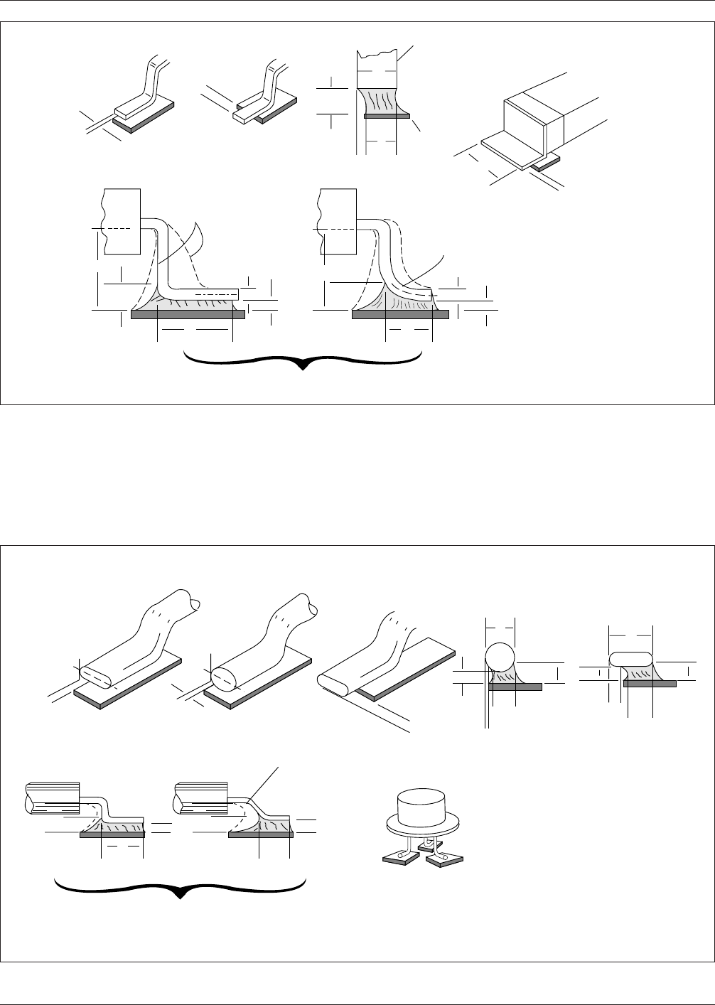
IPC-782-4-6 Figure 4–6 ‘ ‘J’ ’ lead joint description W = Lead Width T = Lead Thickness ▼ ▼ A ▼ W B ▼ ▼ Toe Overhang ▼ ▼ C A ▼ ▼ G ▼ ▼ ▼ ▼ F ▼ ▼ E D ▼ ▼ G See Note 1, Table 9–4 ▼ ▼ Side Overhang T ▼ ▼ End Joint Width Sid…
IPC-782-4-4
Figure 4–4 Flat ribbon, ‘‘L,’’ and gullwing lead joint description
B
▼
▼
A
▼
Side Overhang Toe Overhang
End Joint Width
T
▼
▼
D
▼
▼
▼
E
G
Center Line of "T"
D
▼
▼
E
▼
W = Lead Width
T = Lead Thickness
W
▼
B
▼
▼
Other Lead Configurations
▼
Side Joint Length
▼
▼
▼
▼
Lead
Land
▼
▼
▼
▼
F
▼
▼
▼
▼
CA
▼
G
▼
▼
W
T
▼
▼
▼
G
▼
F
▼
▼
▼
▼
See Note 1
Table 9–2
▼
▼
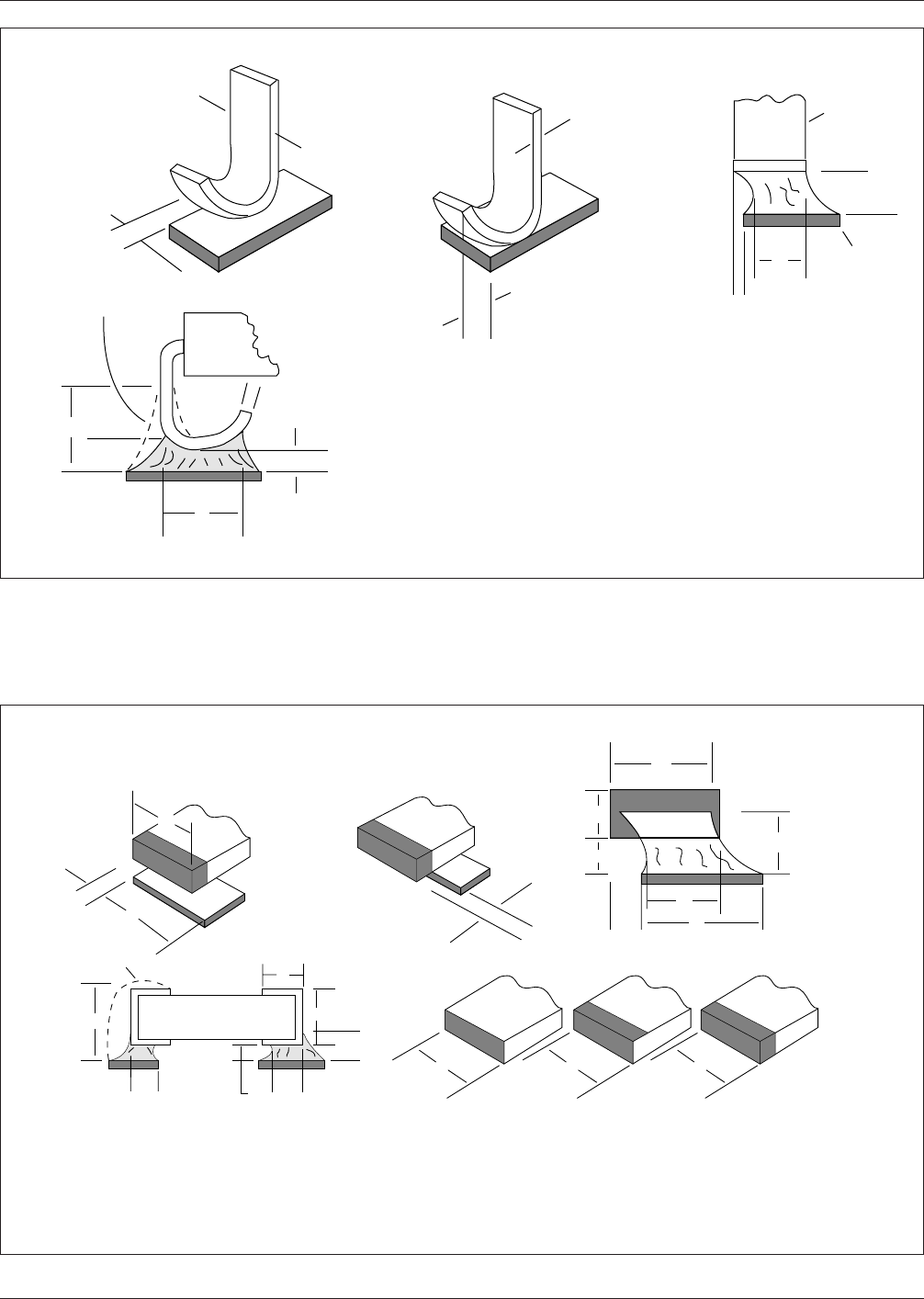
IPC-782-4-5
Figure 4–5 Round or flattened (coined) lead joint description
E
D
▼
▼
▼
▼
W = Flattened Lead
Width or Diameter
of Round Lead
T = Thickness of Lead
at Joint Site (over
land)
Side
Overhang
A
C
A
Q
G
G
C
A
B
W
▼
▼
▼
▼
Q
▼
▼
▼
▼
▼
▼
▼
▼
▼
▼
▼
Other Land
Configurations
D
▼
▼
▼
▼
▼
G
Toe
Overhang
▼
▼
A
Side Joint Length
▼
▼
▼
▼
▼
End
Joint
Width
▼
▼
W
▼
▼
▼
▼
G
E
F
▼
▼
F
▼
▼
▼
▼
See Note 1,
Table 9–3
Note: See ANSI/J-STD-001 for specific details on minimum acceptability requirements.
IPC-SM-782A December 1999
40
IPC-782-4-6
Figure 4–6 ‘‘J’’ lead joint description
W = Lead Width
T = Lead Thickness
▼
▼
A
▼
W
B
▼
▼
Toe
Overhang
▼
▼
C
A
▼
▼
G
▼
▼
▼
▼
F
▼
▼
E
D
▼
▼
G
See Note 1,
Table 9–4
▼
▼
Side
Overhang
T
▼
▼
End Joint Width
Side
Joint
Length
Lead
Land
▼
▼
T
▼
▼
▼
▼
IPC-782-4-7
Figure 4–7 Rectangular or square end components
W =
Width of Termination Area
•
T =
Length of Termination
•
H =
Height of Termination
•
P =
Width of Land
End
Over-
hang
Is Not
Acceptable
B
▼
▼
Three face
termination
Five face
termination
One or
Two-sided
Termination
W
Termination Configurations
▼
▼
W
▼
▼
W
▼
▼
A
Side
Over-
hang
of
Termi-
nation
▼
▼
▼
P
W
▼
P
End Joint Width
F
▼
▼
A
G
▼
▼
▼
▼
H
▼
▼
▼
▼
W
▼
▼
C
▼
▼
E
▼
▼
T
J
▼
▼
D
▼
▼
H
F
G
▼
End Overlap
▼
▼
▼
▼
▼
▼
▼
▼
▼
See Note 1
Table 9–5
Note: See ANSI/J-STD-001 for specific details on minimum acceptability requirements.
December 1999 IPC-SM-782A
41
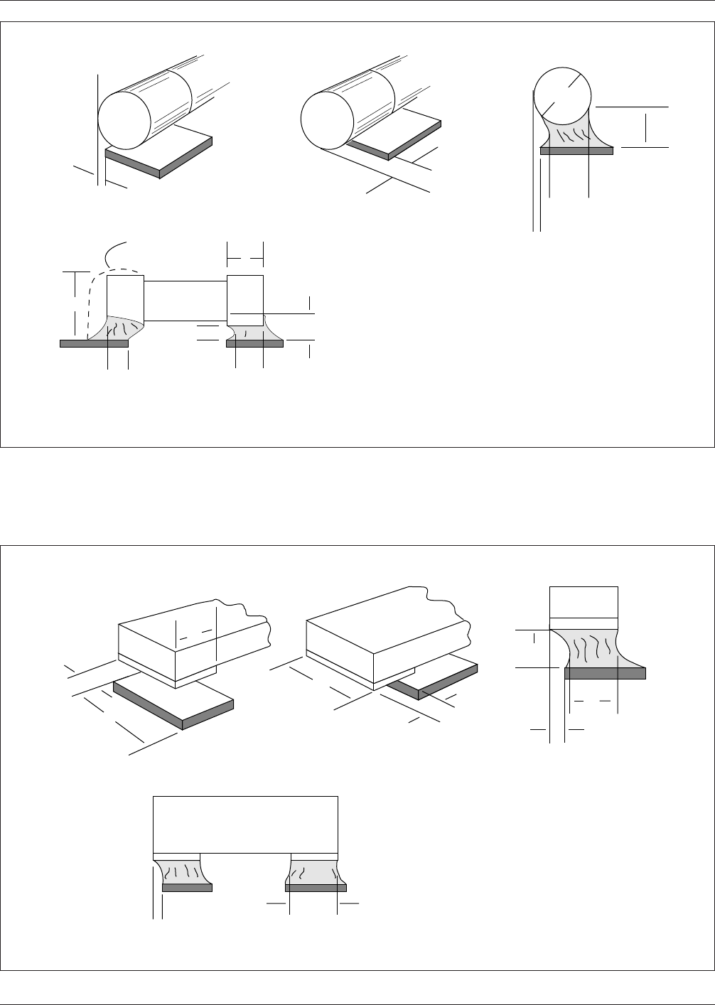
IPC-782-4-8
Figure 4–8 Cylindrical end cap terminations—joint illustration
W = Diameter of
Termination
T = Termination/Plating
Length
A
Side
Overhang
▼
See Note 1
Table 9-6
End
Overhang Is
Not Acceptable
▼
▼
B
C
F
A
End
Joint Width
▼
▼
▼
▼
▼
E
▼
▼
T
D
▼
▼
F
Side Joint Length
and End Overlap
▼
▼
J
▼
▼
▼
▼
▼
▼
G
▼
▼
W
▼
▼
▼
IPC-782-4-9
Figure 4–9 Bottom only terminations
C
A
▼
▼
End Joint Width
▼
G
▼
▼
W = Termination Width
T = Termination Length
P = Land Width
End Overhang
Is Not Acceptable
Side
Overhang
▼
▼
W
▼
A
▼
▼
▼
Side Joint Length
G
▼
▼
D
▼
▼
▼
▼
P
T
▼
B
▼
▼
▼
▼
B
Note: See ANSI/J-STD-001 for specific details on minimum acceptability requirements.
IPC-SM-782A December 1999
42