IPC-SM-782A-表面贴装焊盘图形设计标准.pdf.pdf - 第216页
This Page Intentionally Left Blank IPC-SM-782 Subject 1.0 mm Pitch PBGA JEDEC MO-151 Date 4/99 Section 14.1.3 Revision — P a g e6o f6
RLP Component Identifier
Contact
Array
Rows x
Cols.
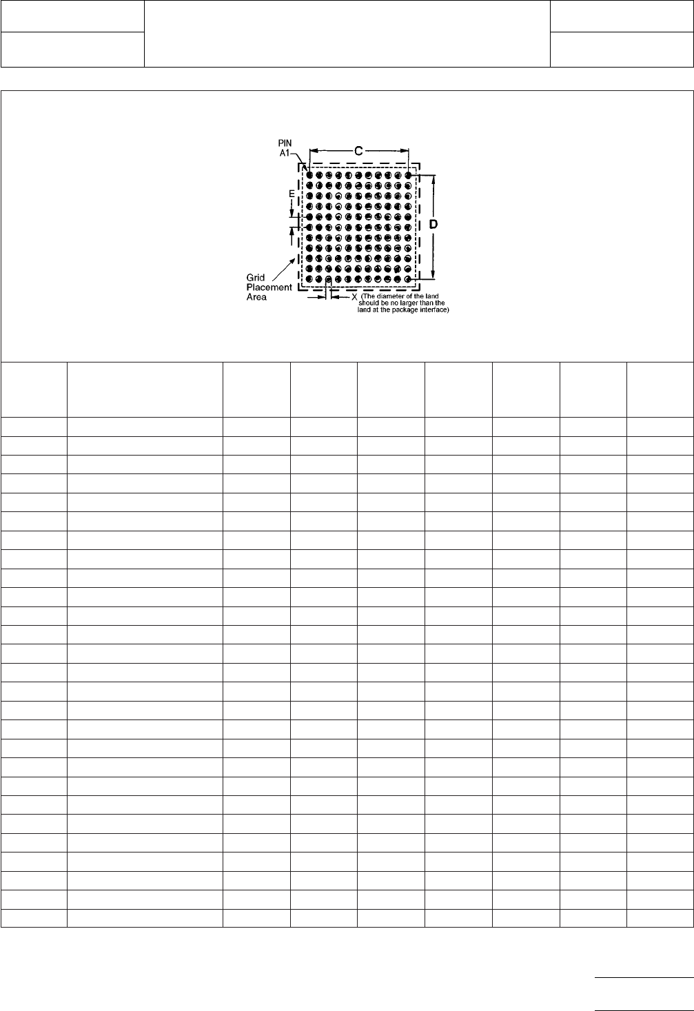
Max.
Contact
Count C D X E
Placement
Grid
923 PBGA 21x21 FO361 19x19 361 18.00 18.00 0.50 1.00 44X44
924 PBGA 23X23 FE484 22X22 484 21.00 21.00 0.50 1.00 48X48
925 PBGA 23x23 FO441 21x21 441 20.00 20.00 0.50 1.00 48X48
926 PBGA 25X25 FE576 24X24 576 23.00 23.00 0.50 1.00 52X52
927 PBGA 25x25 FO529 23x23 529 22.00 22.00 0.50 1.00 52X52
928 PBGA 27X27 FE676 26X26 676 25.00 25.00 0.50 1.00 56X56
929 PBGA 27X27 FO625 25x25 625 24.00 24.00 0.50 1.00 56X56
930 PBGA 29X29 FE784 28X28 784 27.00 27.00 0.50 1.00 60X60
931 PBGA 29X29 FO729 27x27 729 26.00 26.00 0.50 1.00 60X60
932 PBGA 31X31 FE900 30X30 900 29.00 29.00 0.50 1.00 64X64
933 PBGA 31X31 FO841 29x29 841 28.00 28.00 0.50 1.00 64X64
934 PBGA 33X33 FE1024 32X32 1024 31.00 31.00 0.50 1.00 68X68
935 PBGA 33X33 FO961 31x31 961 30.00 30.00 0.50 1.00 68X68
936 PBGA 35X35 FE1156 34X34 1156 33.00 33.00 0.50 1.00 72X72
937 PBGA 35X35 FO1089 33x33 1089 32.00 32.00 0.50 1.00 72X72
938 PBGA 37.5X37.5 FO1369 37X37 1369 36.00 36.00 0.50 1.00 78X78
939 PBGA 37.5X37.5 FE1296 36x36 1296 35.00 35.00 0.50 1.00 78X78
940 PBGA 40X40 FO1521 39X39 1521 38.00 38.00 0.50 1.00 82X82
941 PBGA 40X40 FE1444 38x38 1444 37.00 37.00 0.50 1.00 82X82
942 PBGA 42.5X42.5 FE1764 42X42 1764 41.00 41.00 0.50 1.00 88X88
943 PBGA 42.5X42.5 FO1681 41x41 1681 40.00 40.00 0.50 1.00 88X88
945 PBGA 45X45 FE1936 44X44 1936 43.00 43.00 0.50 1.00 92X92
946 PBGA 45X45 FO1849 43x43 1849 42.00 42.00 0.50 1.00 92X92
947 PBGA 47.5X47.5 FO2209 47X47 2209 46.00 46.00 0.50 1.00 98X98
948 PBGA 47.5X47.5 FE2116 46x46 2116 45.00 45.00 0.50 1.00 98X98
949 PBGA 50X50 FO2401 49X49 2401 48.00 48.00 0.50 1.00 102X102
950 PBGA 50X50 FE2304 48x48 2304 47.00 47.00 0.50 1.00 102X102
Figure 2b PBGA land pattern dimensions
FE = Full Even Matrix
FO = Full Odd Matrix
For land pattern tolerance analysis,
see Section 14.0, Subsection 6.
IPC-SM-782
Subject
1.0 mm Pitch PBGA JEDEC MO-151
Date
4/99
Section
14.1.3
Revision
—
Page5of6

This Page Intentionally Left Blank
IPC-SM-782
Subject
1.0 mm Pitch PBGA JEDEC MO-151
Date
4/99
Section
14.1.3
Revision
—
Page6of6

1.0 SCOPE
This subsection provides the component and land pattern
dimensions for rectangular 1.27 mm pitch Plastic Ball Grid
Arrays (PBGA).
2.0 APPLICABLE DOCUMENTS
The following documents, of the issue in effect on the current
revision date of this section, form a part of this specification to
the extent specified herein.
2.1 Joint Electronic Device Engineering Council
1
JEDEC Publication 95 Registered and Standard Outlines for
Solid State and Related Products:
• Rectangular Plastic Ball Grid Array (R-PBGA), MS-028
3.0 COMPONENT DESCRIPTION
These components are all on 1.27 mm pitch. They are avail-
able in a wide variety of body sizes. The data supplied in the
detail and table reflect a full matrix. Specific contact and
depopulation and pin assignment must be furnished by the
device manufacturer (see Section 14.0 for more information
on depopulation methods).
1. JEDEC: 2500 Wilson Blvd., Arlington, VA, 22201-3834, USA.
IPC-SM-782
Surface Mount Design
and Land Pattern Standard
Date
4/99
Section
14.2
Revision
—
Subject
1.27 mm Pitch
Rectangular PBGA
JEDEC MS-028
Page1of4