00196614-03_AI_Vakuumpumpe_SXDX12_de_en.pdf - 第90页
Fitting the Vacuum Pump Preparatory Steps 3.3.1 Installation Position - Accessibility and Preparations 90 Vacuum Pump Vakuumpumpe 3.3 3 . 3 P r e p a r a t o r y S t e p s Preparatory Steps DX machines are fitted with a …

Fitting the Vacuum Pump
Installation Location
Vacuum Pump Vakuumpumpe 89
3
3 Fitting the Vacuum Pump
Fitting the Vacuum Pump
3.1
3.1 Installation Location
Installation Location
The vacuum pump is installed at location 1 and the connection unit in location 2.
3.2
3.2 Pneumatic and Vacuum Supply
Pneumatic and Vacuum Supply
The following diagram shows the conversion of a machine with two C&P20 A/P heads to vacuum pump
operation.
A maximum of two C&P20 A/P heads can be connected to one vacuum pump.
Preconditions (according to machine configuration) see "2.8 C&P20A/P Placement Head - Special Fea-
tures" [ ➙ 85].
The machine monitors when the vacuum pump is switched on and off e.g. after longer production stand-
still times.
CAUTION
Safety instructions and manufacturer's instructions
In addition to the safety instructions in the introductory chapter, the manufacturer's safety in-
structions, installation and setup instructions apply to the vacuum pump and must be observed.
Avoid switching the placement machine and vacuum pump on and off multiple times within a
short period. This can have a negative influence on the service life of the pump.
The placement machine monitors when the vacuum pump is switched on and off e.g. after long-
er production standstill times.
CAUTION
Switching the compressed air off
Never turn the compressed air on during the conversion, as this could lead to placement head
damage, depending on the installation status.
CAUTION
Gantry with TwinHead or CPP
When using a TwinHead or CPP placement head, never convert the pneumatic supply, gantry
distributor or trailing cable! If you do, there is no guaranty that the TwinHead or CPP will function
properly.
Consequences
CAUTION
Switching the machine on and off
Avoid switching the machine and vacuum pump on and off multiple times within a short period.
This can have a negative influence on the service life of the pump.
Fitting the Vacuum Pump
Preparatory Steps 3.3.1 Installation Position - Accessibility and Preparations
90 Vacuum Pump Vakuumpumpe
3.3
3.3 Preparatory Steps
Preparatory Steps
DX machines are fitted with a manual table as a default. The component trolley is an option.
SX machines are equipped with component trolleys.
Before fitting the pump, make sure that locations 1 and 2 (see "3.3 Preparatory Steps" [ ➙ 90], "3.3.1
Installation Position - Accessibility and Preparations" [ ➙ 90] and "3.3.3 Fitting the Vacuum Pump Con-
nection Unit SX1/2 [03079949-xx] on Machines Kxxx / Lxxx / Mxxx" [ ➙ 100]) plus the trailing cable hos-
es (see "3.3.6 Access to the Trailing Cable Hoses" [ ➙ 106]) are accessible.
► Undock the component trolleys on the SX machines.
► Shut down the station computer and switch off the machine at the main switch.
► Disconnect the machine from the main power and the pneumatic supplies.
► Always secure the machine against unauthorized reactivation. See "1.2 Preparatory Work..." [➙73].
► Remove the manual table from DX machines.
► Remove the waste tape chutes.
Component Supply - Manual Tables - Dismantling Protections - Color Version
3.3.1
3.3.1 Installation Position - Accessibility and Preparations
Installation Position - Accessibility and Preparations
Manual tables only:
► Dismantle the protections:
– Protection waste chute DX1/2 left [03094519-xx]
– Protection waste chute DX1/2 right [03094522-
xx]
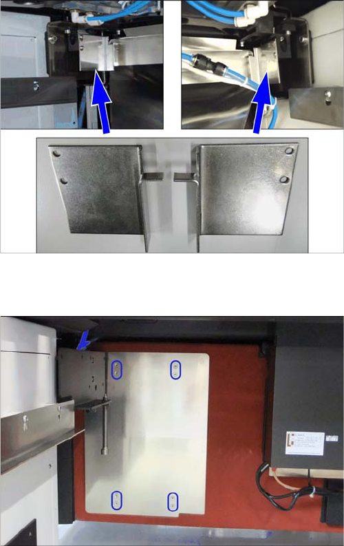
► Remove the vacuum pump cover on the installation
point.
The plate is clipped to four marked positions on the
machine frame. Pull it out towards the front.
Fitting the Vacuum Pump
3.3.1 Installation Position - Accessibility and Preparations Preparatory Steps
Vacuum Pump Vakuumpumpe 91
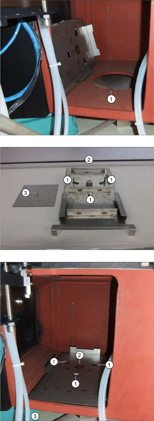
Inserting the Support Plate [03075664-xx]
The support plate, onto which the vacuum pump is fixed,
is placed over the hole (1) and screwed to the mounting
plate from below.
The adjacent photo shows the support plate from below.
1. Nibs for fixture to the machine frame.
2. Fixture point for mounting plate.
3. Mounting plate [03087208-xx] with fastening screw
(DIN7991-M6x16-A2-70) [03051535-xx]
► Position the support plate with the three nibs at posi-
tions 1 facing down and into the hole in the machine
frame (1).
⇨ The nibs fix the support plate to its position.
► From below, position the counterplate against the
mounting plate (3) and screw both into place from be-
low (2).