00196614-03_AI_Vakuumpumpe_SXDX12_de_en.pdf - 第91页
Fitting the Vacuum Pump 3.3.1 Installation Position - A ccessibility and Preparations Pre paratory Steps Vacuum Pump Vakuumpumpe 91 Inserting the Support Plate [03075664-xx] The support plate, onto wh ich the vacuu m pum…
Fitting the Vacuum Pump
Preparatory Steps 3.3.1 Installation Position - Accessibility and Preparations
90 Vacuum Pump Vakuumpumpe
3.3
3.3 Preparatory Steps
Preparatory Steps
DX machines are fitted with a manual table as a default. The component trolley is an option.
SX machines are equipped with component trolleys.
Before fitting the pump, make sure that locations 1 and 2 (see "3.3 Preparatory Steps" [ ➙ 90], "3.3.1
Installation Position - Accessibility and Preparations" [ ➙ 90] and "3.3.3 Fitting the Vacuum Pump Con-
nection Unit SX1/2 [03079949-xx] on Machines Kxxx / Lxxx / Mxxx" [ ➙ 100]) plus the trailing cable hos-
es (see "3.3.6 Access to the Trailing Cable Hoses" [ ➙ 106]) are accessible.
► Undock the component trolleys on the SX machines.
► Shut down the station computer and switch off the machine at the main switch.
► Disconnect the machine from the main power and the pneumatic supplies.
► Always secure the machine against unauthorized reactivation. See "1.2 Preparatory Work..." [➙73].
► Remove the manual table from DX machines.
► Remove the waste tape chutes.
Component Supply - Manual Tables - Dismantling Protections - Color Version
3.3.1
3.3.1 Installation Position - Accessibility and Preparations
Installation Position - Accessibility and Preparations
Manual tables only:
► Dismantle the protections:
– Protection waste chute DX1/2 left [03094519-xx]
– Protection waste chute DX1/2 right [03094522-
xx]
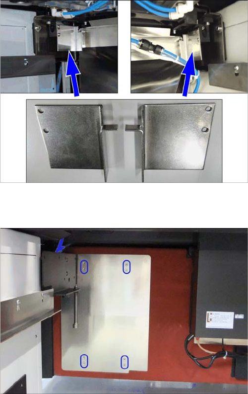
► Remove the vacuum pump cover on the installation
point.
The plate is clipped to four marked positions on the
machine frame. Pull it out towards the front.
Fitting the Vacuum Pump
3.3.1 Installation Position - Accessibility and Preparations Preparatory Steps
Vacuum Pump Vakuumpumpe 91
Inserting the Support Plate [03075664-xx]
The support plate, onto which the vacuum pump is fixed,
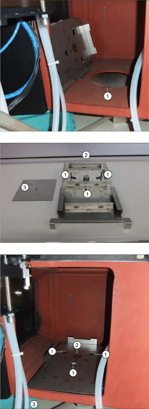
is placed over the hole (1) and screwed to the mounting
plate from below.
The adjacent photo shows the support plate from below.
1. Nibs for fixture to the machine frame.
2. Fixture point for mounting plate.
3. Mounting plate [03087208-xx] with fastening screw
(DIN7991-M6x16-A2-70) [03051535-xx]
► Position the support plate with the three nibs at posi-
tions 1 facing down and into the hole in the machine
frame (1).
⇨ The nibs fix the support plate to its position.
► From below, position the counterplate against the
mounting plate (3) and screw both into place from be-
low (2).
Fitting the Vacuum Pump
Preparatory Steps 3.3.2 Prefitting the Vacuum Pump
92 Vacuum Pump Vakuumpumpe
3.3.2
3.3.2 Prefitting the Vacuum Pump
Prefitting the Vacuum Pump
Before the pump can be fitted, it needs to be prepared. This preparation work covers the following tasks:
▪ "3.3.2.1 Closing the Opening Mechanism" [ ➙ 92]
▪ "3.3.2.2 Connecting the Power cable" [ ➙ 93]
▪ "3.3.2.4 Fitting and Positioning the Filter" [ ➙ 95]
▪ "3.3.2.5 Preparing and Connecting the Distributor Block" [ ➙ 97]
▪ "3.3.2.7 Placing the Vacuum Pump onto the Slide" [ ➙ 98]
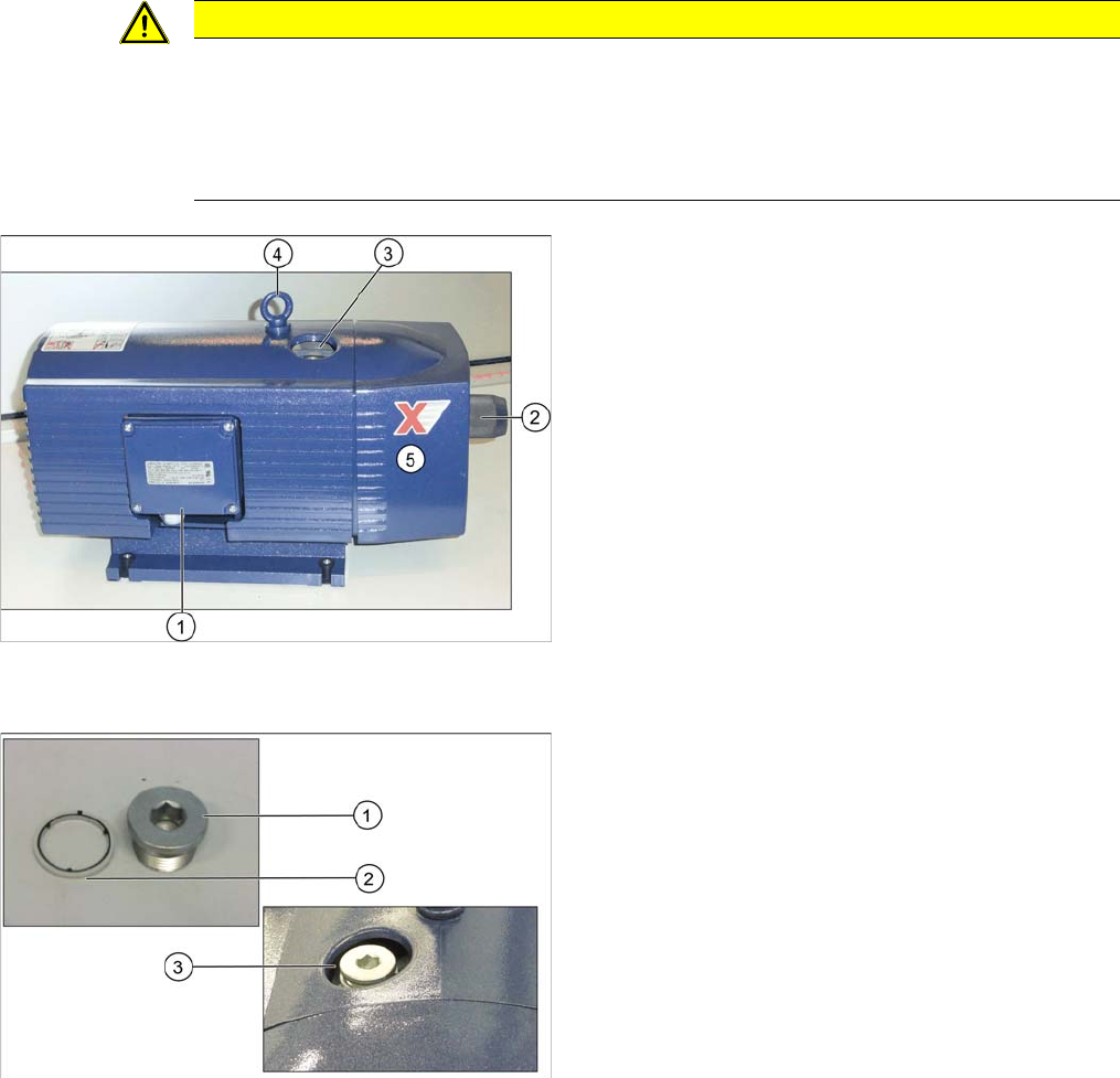
Vacuum pump in original state
3.3.2.1
3.3.2.1 Closing the Opening Mechanism
Closing the Opening Mechanism
CAUTION
Lifting the vacuum pump
► When lifting the vacuum pump, always take hold of its base. As its center of gravity is above
this base, parts of the pump could be pulled off if you take hold of it elsewhere.
► Never lift the vacuum pump by its front plate! The front plate of the vacuum pump is only
fixed with rubber buffers. Take care not to damage the rubber buffers.
1. Cover on electricity connection box
2. Vacuum valve [03109300-xx]
3. Opening mechanism
4. Eyelet
5. Front plate
► You may need to replace the eyelet with ISO4762-
M10x25-A2-70 [03042599-xx]
1. Sealing plugs
2. Sealing ring
3. Opening mechanism
► If not prefitted, position the sealing ring (2) on the
sealing screw (R3/4 St+NBR) [03004775-xx] (1) and
screw both into the opening on the top of the pump
(3).
If there is no sealing ring available, first apply Loctite
55 onto the threaded connection as a sealant.