00196614-03_AI_Vakuumpumpe_SXDX12_de_en.pdf - 第92页
Fitting the Vacuum Pump Preparatory Steps 3.3.2 Prefitting the Vacuum Pump 92 Vacuum Pump Vakuumpumpe 3.3.2 3 . 3 . 2 P r e f it t in g t h e V a c u u m P u m p Prefitting the Vacuum Pump Before the pump can b e fitted,…
Fitting the Vacuum Pump
3.3.1 Installation Position - Accessibility and Preparations Preparatory Steps
Vacuum Pump Vakuumpumpe 91
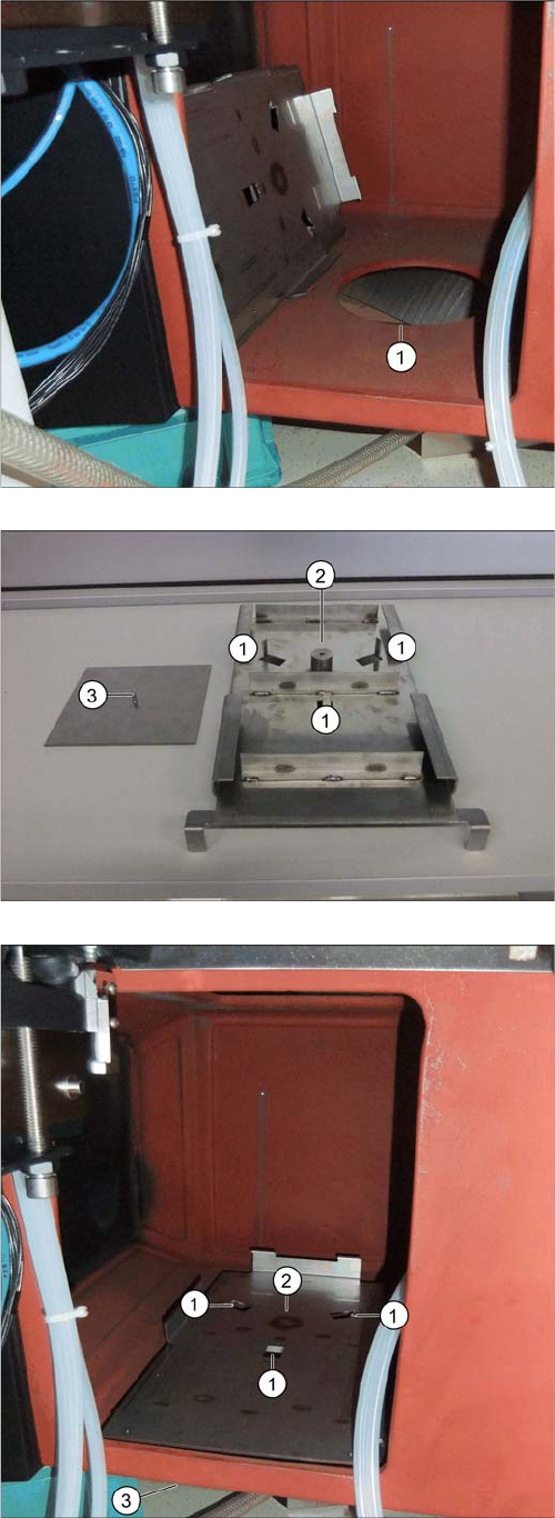
Inserting the Support Plate [03075664-xx]
The support plate, onto which the vacuum pump is fixed,
is placed over the hole (1) and screwed to the mounting
plate from below.
The adjacent photo shows the support plate from below.
1. Nibs for fixture to the machine frame.
2. Fixture point for mounting plate.
3. Mounting plate [03087208-xx] with fastening screw
(DIN7991-M6x16-A2-70) [03051535-xx]
► Position the support plate with the three nibs at posi-
tions 1 facing down and into the hole in the machine
frame (1).
⇨ The nibs fix the support plate to its position.
► From below, position the counterplate against the
mounting plate (3) and screw both into place from be-
low (2).
Fitting the Vacuum Pump
Preparatory Steps 3.3.2 Prefitting the Vacuum Pump
92 Vacuum Pump Vakuumpumpe
3.3.2
3.3.2 Prefitting the Vacuum Pump
Prefitting the Vacuum Pump
Before the pump can be fitted, it needs to be prepared. This preparation work covers the following tasks:
▪ "3.3.2.1 Closing the Opening Mechanism" [ ➙ 92]
▪ "3.3.2.2 Connecting the Power cable" [ ➙ 93]
▪ "3.3.2.4 Fitting and Positioning the Filter" [ ➙ 95]
▪ "3.3.2.5 Preparing and Connecting the Distributor Block" [ ➙ 97]
▪ "3.3.2.7 Placing the Vacuum Pump onto the Slide" [ ➙ 98]
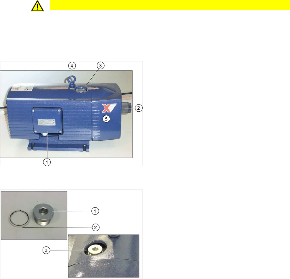
Vacuum pump in original state
3.3.2.1
3.3.2.1 Closing the Opening Mechanism
Closing the Opening Mechanism
CAUTION
Lifting the vacuum pump
► When lifting the vacuum pump, always take hold of its base. As its center of gravity is above
this base, parts of the pump could be pulled off if you take hold of it elsewhere.
► Never lift the vacuum pump by its front plate! The front plate of the vacuum pump is only
fixed with rubber buffers. Take care not to damage the rubber buffers.
1. Cover on electricity connection box
2. Vacuum valve [03109300-xx]
3. Opening mechanism
4. Eyelet
5. Front plate
► You may need to replace the eyelet with ISO4762-
M10x25-A2-70 [03042599-xx]
1. Sealing plugs
2. Sealing ring
3. Opening mechanism
► If not prefitted, position the sealing ring (2) on the
sealing screw (R3/4 St+NBR) [03004775-xx] (1) and
screw both into the opening on the top of the pump
(3).
If there is no sealing ring available, first apply Loctite
55 onto the threaded connection as a sealant.
Fitting the Vacuum Pump
3.3.2 Prefitting the Vacuum Pump Preparatory Steps
Vacuum Pump Vakuumpumpe 93
3.3.2.2
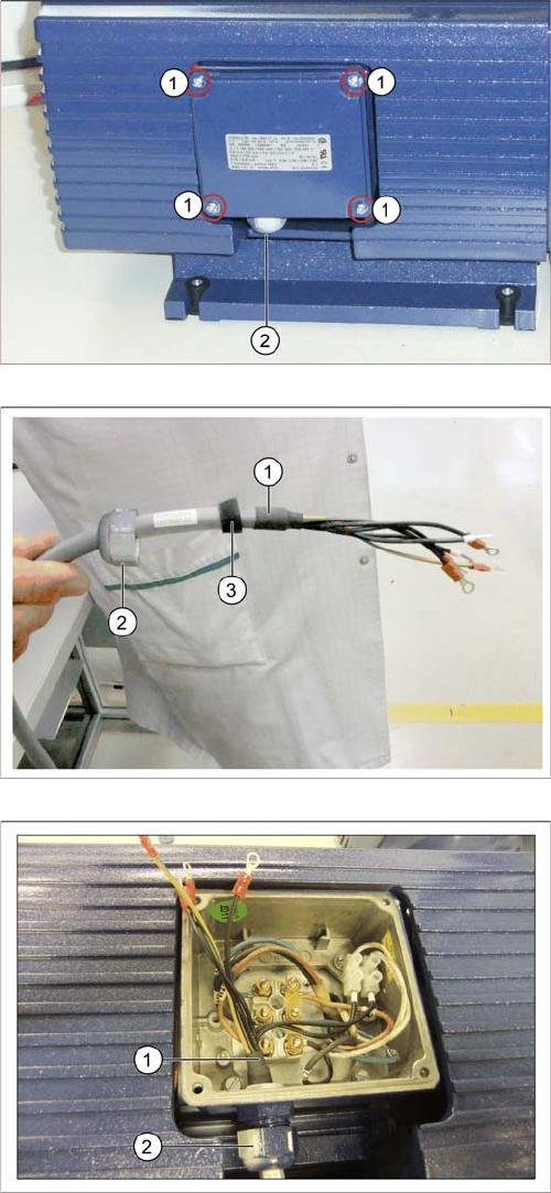
3.3.2.2 Connecting the Power cable
Connecting the Power cable
1. 4 screws on the cover
2. Tension relief
► Remove the four screws (1) fastening the cover on
the electricity connection box and then remove the
cover.
► Turn the strain relief out (2).
1. Power cable
2. Tension relief
► Thread the power cable [03079997-xx] (1) through
the strain relief (2) and the sealing ring (3).
1. Power cable
2. Tension relief
► Thread the power cable into the electricity connection
box (1) and turn the strain relief until tight (2).