DFD6361-Maintenance.pdf - 第100页
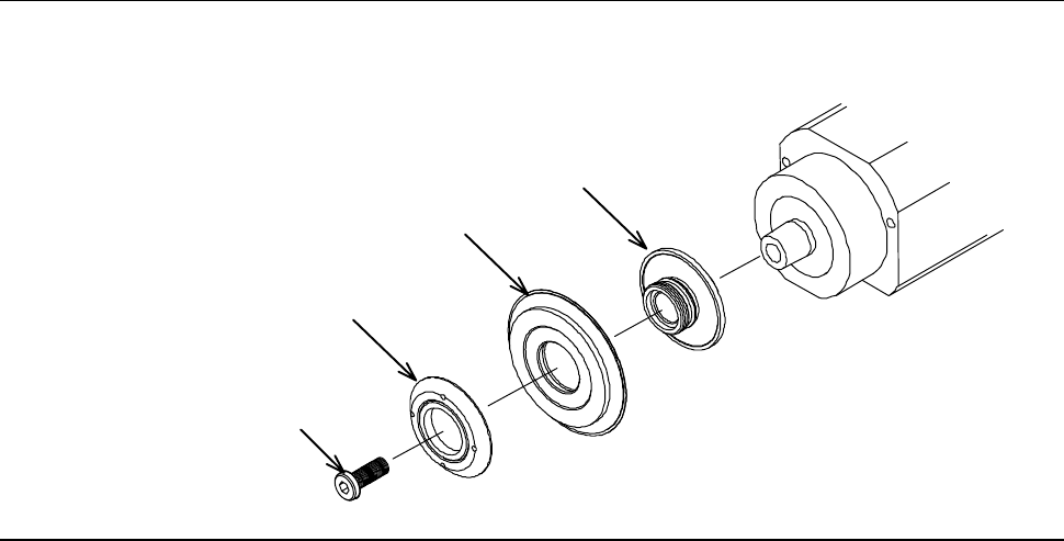
B-28 Exploded view of hub mount and blade ( 1.2 k W spindle) The hub mount and blade are to be mounted as illustrated below . [1.2 k W S pindle: 2-i nch T ype] Hub mount Hub blade Lock nut for hub Lock bolt
B-27
2-2-1. Removing the hub mount (1.2 kW spindle)
Safety precautions for removing the hub mount (1.2 kW spindle)
WARNING
In the hub removal operation, you have to touch the spindle-axis
section and axis operating section directly by your hands. If the
spindle is not stopped, your hands or fingers may be caught or cut
off.
- Before opening the splash cover, visually make sure from outside
of the cover that the spindle is completely stopped.
- Ensure that no other person touches the machine during operation.
- While you don't use the touch panel, press the Disco's logo
button located at the upper left of the screen in order to lock up
and deactivate the touch panel.
CAUTION
In hub mount removal/installation, observe the following precautions
to prevent the spindle from damage.
- Before starting replacement, call up and display the BLADE
REPLACEMENT screen [screen 4.1].
- Make sure that air is supplied to the spindle.
- Be sure to apply force only in the direction of cocentral of spindle
axis (Y-axis direction).
B-28
Exploded view of hub mount and blade (1.2 kW spindle)
The hub mount and blade are to be mounted as illustrated below.
[1.2 kW Spindle: 2-inch Type]
Hub mount
Hub blade
Lock nut for hub
Lock bolt
B-29
Procedures for removing the hub mount (1.2 kW spindle)
Step No. Do This
1
Call up the BLADE REPLACEMENT screen [screen 4.1].
- The Y-axis moves to its origin position.
2
Make sure that the spindle is OFF.
3
Press the Disco's logo button located at the upper left of the
screen to lock up the touch panel.
4
Open the splash cover.
5
Remove the lock nut for hub and blade.
- For procedures to remove them;
See the section B-6 of Operation Manual, [Blade Maintenance].
6
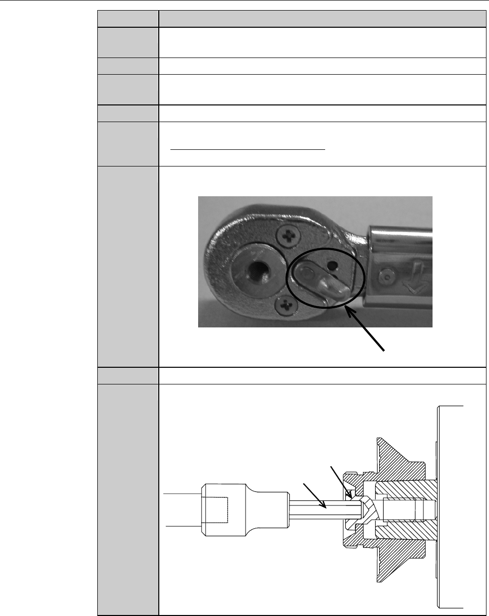
Adjust the direction selector lever so that the wrench does not
turn free when you turn the torque wrench counterclockwise.
Direction selector lever
7
Have on hand the torque wrench set.
8
Insert the bit into the center hole of the lock bolt.
Lock bolt
Bit