DFD6361-Maintenance.pdf - 第258页
C-46 USER DEFIN E DATA scr een [screen 7.4 ] (Continued) [Setting Ite m] Item No. Descriptions [14] Specify whether or not to retain any cutting speed changed during cutting when the relevant device data cutting is com p…

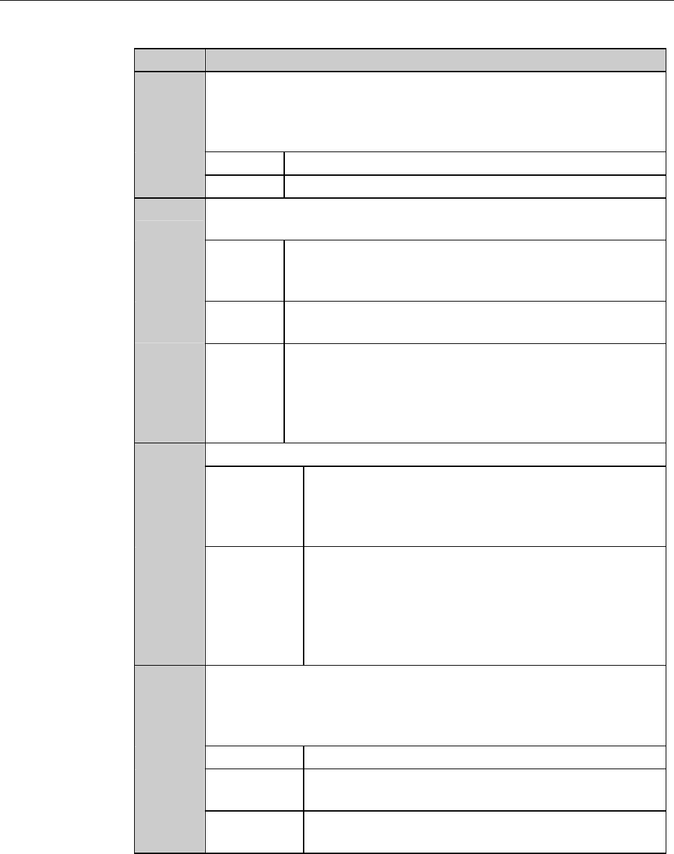
C-45
USER DEFINE DATA screen [screen 7.4] (Continued)
[Setting Item]
Item No. Descriptions
[4]
Enter the user password for calling up the MACHINE
MAINTENANCE screen [screen 6.0].
- If no password is entered here, the system does not prompt for
password input.
- User password protected screens can be opened by the
engineering password.
- The factory preset user password is "123".
[5]
Enter the engineering password for calling up the ENGINEERING
MAINTENANCE screen [screen 7.0].
- If no password is entered here, the system does not prompt for
password input.
- Engineering password protected screens cannot be opened by
other passwords.
- The factory preset engineering password is "123".
[6]
When the <F1> button is pressed from the ENGINEERING
MAINTENANCE screen [screen 7.0] to select the conditioning
operation, the spindle automatically moves. You can specify the
spindle destination in this column.
When a minus value is entered, the Z1-axis side spindle is
automatically moves to rearward from the chuck table center.
[7]
Enter the limit value for the correction distance during the hairline
alignment.
[8]
Enter the table blow-release time for the chuck table vacuum OFF
sequence.
[9]
Enter the table blow-release time for the spinner table vacuum
OFF sequence.
[10]
Specify the length of interval between the spinner cleaning water
turning ON and initiation of monitoring of the cleaning water
pressure.
[11]
Enter the correction value for θ-axis rotation accuracy. This
correction value is effective only for 90-degree rotation.
[12]
Energy-efficient function. The machine measures the length of
time while any operation such as alignment, cut or full automation
is not performed. If no operation is made for a given length of
time, the machine automatically turns OFF the power of the motor
driver and stops air supply.
Specify the time between establishment of the energy-saving mode
and the last machine operation. If zero is entered here, this
function does not work. Note that system initial is required when
the energy-saving mode is canceled.
[13]
Select the language to be used on the screen.
C-46
USER DEFINE DATA screen [screen 7.4] (Continued)
[Setting Item]
Item No. Descriptions
[14]
Specify whether or not to retain any cutting speed changed during
cutting when the relevant device data cutting is completed. If you
select to retain, the modified speed will be used for the next device
data to be cut.
KEEP Retains the changed cutting speed.
CLEAR Clears the changed cutting speed.
[15]
Specify whether or not to permit cutting speed changes during
cutting.
YES Allows you to change the speed no matter whether a
cutting operation is in progress or is temporarily
halted.
NO You cannot change the speed while the cutting
operationisinprogress.
SPEED Permits you to change the speed no matter whether a
cutting operation is in progress or is temporarily
halted. However, if a newly entered speed is higher
than the cutting speed defined by the device data, it is
not accepted.
[16]
Specify the error output mode when a blade breakage is detected.
Z-EM Z-EM operation is immediately performed when a
blade breakage is detected.
In this mode, the error output is generated even in
the middle of one-line cutting.
RECHECK Rechecks the blade breakage after completion of the
current line cutting operation when a blade
breakage is detected.
If a blade breakage is confirmed in the recheck, the
machine indicates the error and stops the cutting
operation.
[17]
Specify whether or not to use the already-cut-work-check function
in the alignment process. If a cut line is detected in a kerf check
which is conducted after individual channel street adjustments in
the alignment process, the error is indicated.
NO No use the above-mentioned check function.
FIRST Confirms only the first workpiece in the cassette in
the FULL AUTO mode operation.
ALWAYS Confirms all the workpieces in the FULL AUTO
mode operation.
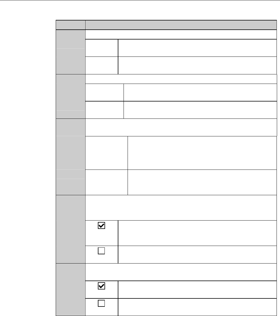
C-47
USER DEFINE DATA screen [screen 7.4] (Continued)
[Setting Item]
Item No. Descriptions
[18]
Specify a frame detection mode for push-pull frame loading.
SENSOR Detects a frame by the optical sensor which is located
to the left of the clamp finger section.
CLAMP Detects a frame in accordance with the clamp finger
cylinder movement width.
[19]
Specify the starting position of workpiece loading.
TOP-SIDE Starts to load workpiece from the top slot of the top
cassette.
BOTTOM Starts to load workpiece from the lowest slot of the
lowest cassette.
[20]
Specify whether or not to suspend or resume processing when an
inspection workpieces returns to the stage.
STOP Suspends processing and makes no transportation
for other workpiece until the inspection of the
sample workpiece finishes and the workpiece
returns to the cassette.
CONTINUE Continues processing for other workpieces, without
waiting for the inspection workpiece returning to
the stage.
[21]
Specify whether or not to permit cutting height modification
during cutting. (The value changed during cutting will be cleared
when the setup is completed.)
Allows you to change the cutting height no matter
whether a cutting operation is in progress or is
temporarily halted.
Height correction cannot be made during cutting but
can be done while the cutting is temporarily halted.
[22]
Specify whether or not to stop the spindle and wheel coolant water
systems when some blade breakage is detected.
Stops the spindle and wheel coolant water system
automatically when a blade breakage is detected.
The spindle and wheel coolant water system do not
stop even when a blade breakage is detected.