DFD6361-Maintenance.pdf - 第161页
B-89 Procedur es for mo unting the hub moun t (2.2 k W spindle) (Conti nued) St e p N o . Do This 7 Close the spla sh cover . 8 Press the <C lose> button to release l ock of the t ouch panel. 9 Press the <EXIT&g…
B-88
Procedures for mounting the hub mount (2.2 kW spindle)
Step No. Do This
(Continued from the previous section)
1
Clean the hub mount and spindle taper section with lint-free
waste moistened with alcohol, and then blow air to remove water.
2
Fit the hub mount onto the spindle taper section.
3
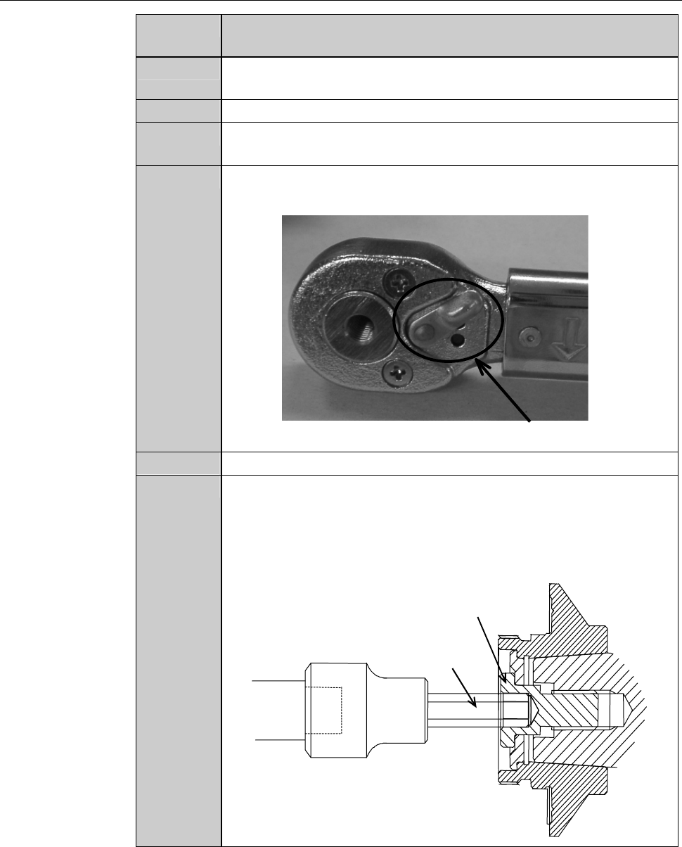
Adjust the torque of the torque wrench.
Torque for 2.2kW spindle: 8.0 N·m
4
Adjust the direction selector lever so that specified torque will be
produced when you turn the torque wrench clockwise.
Direction selector lever
5
Have on hand the torque wrench set.
6
Using the torque wrench set, torque the lock bolt to 8.0 N·m.
- To tighten the bolt, turn the torque wrench clockwise.
- Turn the torque wrench slowly.
- When the torque reaches the specified one, you feel light
resistance.
Lock bolt
Bit
B-89
Procedures for mounting the hub mount (2.2 kW spindle) (Continued)
Step No. Do This
7
Close the splash cover.
8
Press the <Close> button to release lock of the touch panel.
9
Press the <EXIT> button to call up the MAIN MENU
[screen 0.0].
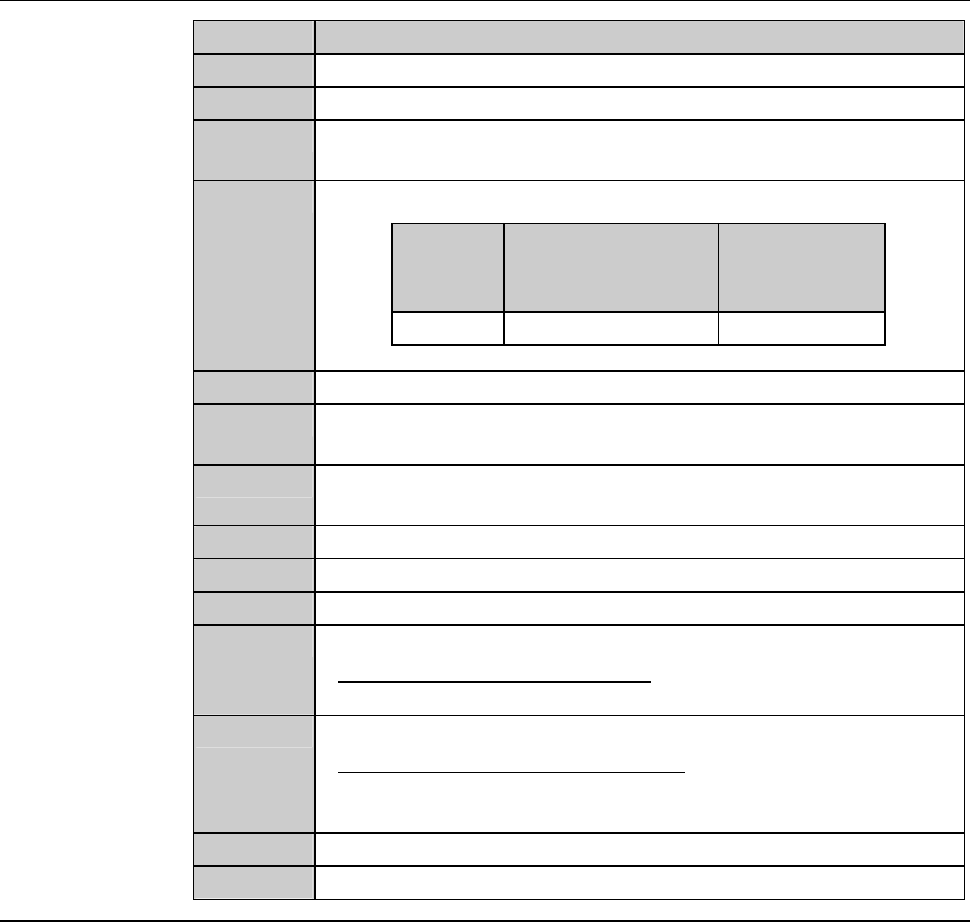
10
Turn ON the spindle.
Blade
diameter
[inch]
Maximum spindle
rotating speed
[min
-1
(rpm)]
Time to reach
maximum
speed [s]
3 30,000 30
11
Turn OFF the spindle.
12
Call up the BLADE REPLACEMENT screen [screen 4.1].
- The Y-axis moves to its origin position.
13
Press the Disco's logo button located at the upper left of the
screen to lock up the touch panel.
14
Open the splash cover.
15
Torque the lock bolt to 8.0 N·m again.
16
Press the <Close> button to release lock of the touch panel.
17
Perform a conditioning operation.
- For the conditioning procedures;
See the section C-2, [Hub Mount/Flange Conditioning].
18
Install the blade.
- For the blade installation procedure;
See the section B-6, [Blade Maintenance] of the Operation
Manual.
19
Close the splash cover.
20
Press the <System Initial> button to effect system initialization.
B-90
3. Changing the Frame Size
Operation flow
This section describes how to change the pad position of the lower arm and
upper arm, size of chuck table frame clamp and how to replace the spinner
table.
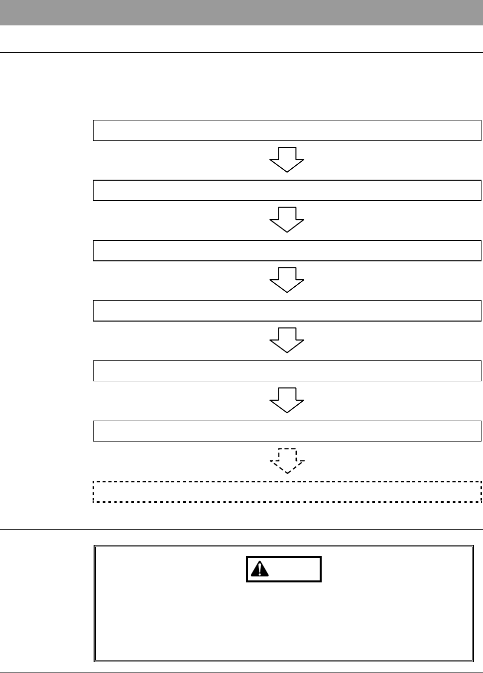
The procedure for changing the frame size consists of the following steps.
3-1 Calling up the CHANGE FRAME SIZE Screen
3-2 Changing the Lower Arm Size
3-3 Changing the Upper Arm Size
3-4 Replacing the Spinner Table
3-5 Changing the Frame Clamp Size
3-6 Completion of Frame Size Change
3-7 Changing UV Irradiation Unit Frame Size [Optional Accessory]
Safety precautions for changing the frame size
WARNING
If the touch panel control is activated to invoke an unexpected
machine operation, the operator may be injured.
While you don't use the touch panel, press the Disco's logo button
located at the upper left of the screen in order to lock up and
deactivate the touch panel.