JX-300LED_SPE_EN01.pdf - 第14页
- 10 - 4.4 Nozzles V arious types of nozzles have been designed to increase the reliability of placement of each type of components as shown in the t able below . For a standard nozzle t o be attached on the JX-300LED, s…
- 9 -
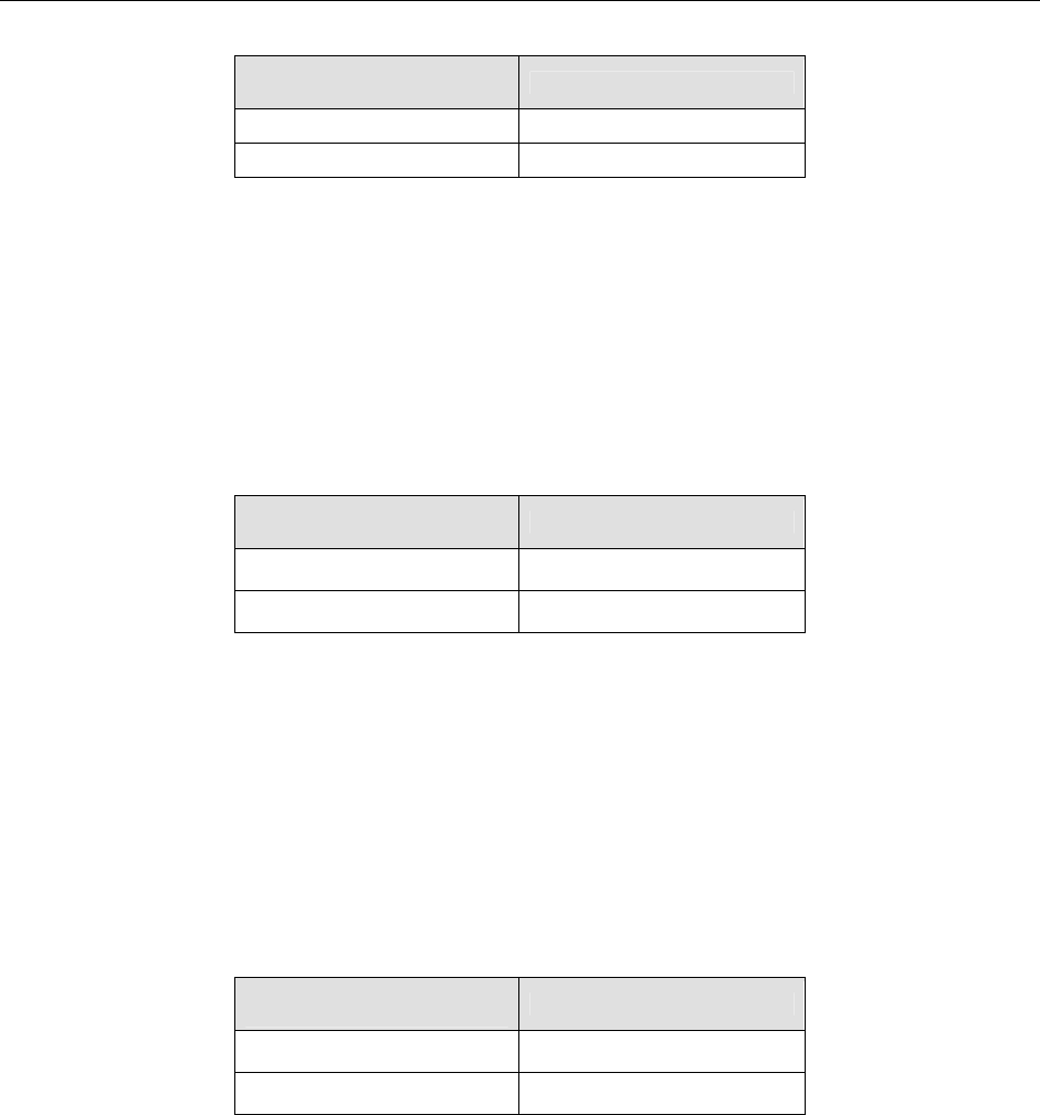
4.3 Component Placement Cycle Time
(Number of Components Placed for One Hour)
(1) 1005 Square chip (conforming to IPC9850)
Component height
specifications
Cycle time (CPH)
SC(6mm) 19,300
NC(12mm) 18,800
*1 This is a number of components to be placed for one hour when 400 1005 square chips are
placed onto a 200 mm×200 mm board whose thickness is 2.5 mm at an angle of 0, 90 180 and
270 degrees sequentially. (This operation conforms to IPC9850.)
*2 This cycle time is measured when an 8-mm tape feeder is used, and components are placed on
boards sequentially after the L1 to L6 nozzles are used to pick them up simultaneously and a
component existence check is run.
*3 This measurement is performed under the optimal conditions except for the check functions
such as a component tombstone error.
(2) LED square chip
Component height
specifications
Cycle time (CPH)
SC(6mm) 18,200
NC(12mm) 17,300
*1 This is a number of components to be placed for one hour when LED square chips are placed
on boards sequentially according to the JUKI designated placement pattern. (This figure does
not include any mark recognition time.)
*2 This cycle time is measured when Six feeders(12-mm tape) is used, and components are
placed on boards sequentially after the L1, L3 and L5 nozzles are used to pick them up
simultaneously, the L2, L4 and L6 nozzles are used to pick them up simultaneously and a
component existence check is run.
*3 This measurement is performed under the optimal conditions except for the check functions
such as a component tombstone error.
(3) LED diffusing lens
Component height
specifications
Cycle time (CPH)
SC(6mm) -
NC(12mm) 10,000
*1 This is a number of components to be placed for one hour when LED diffusing lenses are placed
on boards sequentially according to the JUKI designated placement pattern. (This figure does
not include any mark recognition time.)
*2 This cycle time is measured when Six feeders(12-mm tape) is used, and components are
placed on boards sequentially after the L1, L3 and L5 nozzles or the L2, L4 and L6 nozzles are
used to pick up three lenses simultaneously and a component existence check is run.
*3 This measurement is performed under the optimal conditions except for the check functions
such as a component tombstone error.
- 10 -
4.4 Nozzles
Various types of nozzles have been designed to increase the reliability of placement of
each type of components as shown in the table below.
For a standard nozzle to be attached on the JX-300LED, select it from among the nozzles
shown in the table below.
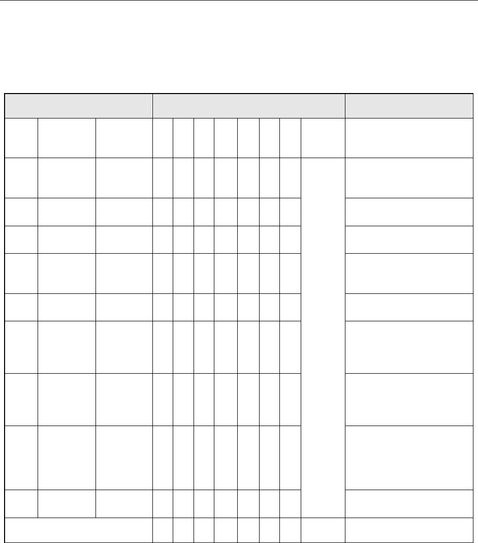
Table Nozzles supplied as the standard devices
Nozzle Nozzle assembly
Applicable components
(reference) and remarks
NO.
Internal
diameter
of a nozzle
External
diameter
of a nozzle
A B D E F G H
Std.
Nozzle
select
500 2-φ0.4 1.0 x 0.5 − 6 − − − − −
1005, 1608, 2012
See Note2
SOT (Molding: 1.6 x 0.8)
501 φ0.25 0.7 x 0.4 − − 6 − − −
0603
502 φ0.4 φ0.7 6 − 6 3 − − 3
1005
503 φ0.6 φ1.0 6 − 3 6 3 6 3
1608, 2012, SOT (Molding:
1.6 x 0.8), SOT (Molding:
2.0 x 1.25)
504 φ1.0 φ1.5 − 4 1 3 6 6 3
2012, 3216, SOT23, SOT
(Molding: 2.0 x 1.25)
505 φ1.7 φ3.5 1 2 − 3 3 1 3
Aluminum electrolytic
capacitor
(small), tantalum electrolytic
capacitor, trimmer
506 φ3.2 φ5.0 1 1 − 1 3 1 3
Aluminum electrolytic
capacitor (medium),
SOP (narrow type),
SOJ, Connector
507 φ5.0 φ8.5 1 1 − − 1 1 1
Aluminum electrolytic
capacitor (large),
SOP (wide type),
TSOP, QFP, PLCC,
Connector
508C φ8.0 φ9.5 1 1 1 1 1 1 1
See
Note1
QFP, PLCC, BGA
Total number of nozzles 16 15 17 17 17 16 17 15
* Total number of nozzles that can be installed onto an ATC station: 26 pieces.
Note 1: As a Std. Nozzle Select, you can select 15 nozzles among those whose number is from
500 to 508C.
However, you have to select a nozzle to be used for calibration of the machine:
- For laser calibration (one of the nozzles choose from 500, 502 and 503)
- For calibration (508C nozzle)
Note 2: Since a theta error may occur due to the shape of the surface of a 2012R component to
be picked, use a No. 504 nozzle if you have to place 2012R components in the high
density (the gap between the adjacent components: 0.3 mm or less).
- 11 -
4.5 Applicable Components
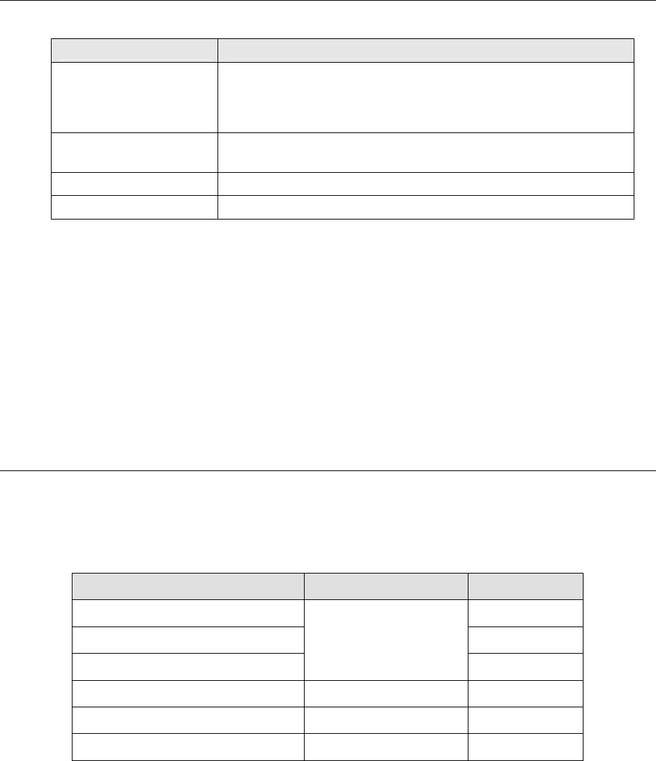
4.5.1 Applicable component sizes
Laser recognition (LNC60)
Component size
(Length × Width)
Minimum: 0.6 × 0.3mm
Maximum: 33.5mm
(33.5mm on a side)
Component height
SC specification: 0.09 mm (for a 0603 component) to 6.0 mm
NC specification: 0.09 mm (for a 0603 component) to 12.0 mm
Lead pitch 0.65mm or more
Ball pitch 1.0mm ~ 1.27mm
Note 1: The maximum size of components that can be recognized with 6 nozzles of the LNC60
at the same time is □ 10.0 mm.
When you are to place components whose size is more than □ 10.0 mm with the
LNC60 head, only three heads are used to pick them up.
Note 2: The described maximum dimensions of a component are applicable if a pick-up error of
the XY dimensions is ± 1 mm or less and the angle error is ± 3
°
or less.
Note 3: Components
☐
20 mm to
☐
33.5 mm can be used with the L3 or L4 head only.
Note 4: Components whose dimensions are 26.5 mm
×
11.0 mm are available even
4.6 Component Placement Accuracy at X, Y and
θ
- The regulated value of a component to be recognized with laser is “Cpk ≧ 1.”
- The accuracy shall be the absolute value from the component reference mark or PWB
reference mark.
Component type XY
θ
Square chip (0603) ±3°
Square chip (1005) ±2.5°
Square chip(1608 or larger)
±50μm
±2°
Square chip (LED) ±50μm ±3°
SOT ±0.15mm ±3°
Aluminum electrolytic capacitor ±0.3mm ±10°
Adjacent pitch
- 0603: 0.20mm