JX-300LED_SPE_EN01.pdf - 第36页
- 32 - 7. Control System 7.1 Control 7.1.1 Saving a program The machine stores a production program onto the SSD in the main unit. When you use a USB port, you can store it on an external storage device also. 7.1.2 Limit…
- 31 -
6.4.3 Options
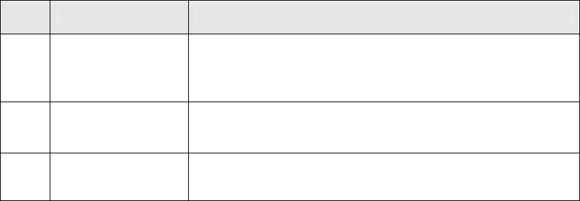
No. Description TR5SNR Option (
See Note 1
.)
①
Ultra-slow mode
(
See Note 2
)
To pull out/store the tray base to which components are supplied,
this function changes the motor/cylinder speed to a low speed in
order to prevent components from jumping out. This speed setting
is performed by a production program.
②
Stacker with
opening/closing cover
To prevent the tray base from jumping out when setting the tray
base in the stacker, this stacker is provided with a cover for fixing
the tray base without level difference of the tray base.
③
2-inch
waffle tray holder
Tray holder for setting a ☐50-mm waffle tray
Note1:The above functions of the TR series are factory-set options.
Note2:Ultra-slow mode is displayed as “Low speed 2” on the operation screen of the machine.
- 32 -
7. Control System
7.1 Control
7.1.1 Saving a program
The machine stores a production program onto the SSD in the main unit.
When you use a USB port, you can store it on an external storage device also.
7.1.2 Limit of a production program
- Maximum number of placement points per circuit :3,000 points
- Maximum number of circuits per PWB :1,200 for a matrix board
200 for a non-matrix board
- Maximum number of points per PWB :10,000 points
- Maximum number of component data records :Maximum number of component
types that can be attached on the
machine
- Maximum number of component pick-up records :Same as the above.
- Maximum number of registered marks :50 sets of area marks/component
positioning marks
- Number of necessary BOC marks :When the X-aixs of a board
Up to 610 mm : 1 set (2 to 3 marks)
From 610 to 1,200 mm : 2 sets (4 to 6 marks)
From 1,200 to 1,500 mm : 3 sets (6 to 9 marks)
7.2 Production Mode
The following three production modes are available during production:
PWB production
- Specifies the number of PWBs you plan to produce and produces PWBs actually.
Trial mode
- Performs a trial PWB production.
You can select the PWB pick-up position tracking function or PWB placement position
tracking function that is to be performed after placement.
Dry run mode
- Checks the PWB pick-up/placement process without using any component.
You can select the PWB pick-up/placement position tracking function.
- 33 -
8. Other Specifications
8.1 Electrical interfaces
8.1.1 Kinds and meanings of electrical signals
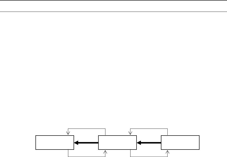
The conceptual diagram of the electrical signals both on the machines and the other side
machines is shown, as follows: The electrical signals between the machines and
upstream-side devices ①, ② and between the machines and downstream-side devices
③, ④ is shown in the following diagram.
a) The electrical signal ① is called the “carryout request input signal (or PWBs
available-in),” receiving the PWBs carryout requests from the upstream-side devices.
b) The electrical signal ② is called the “carryout permit output signal (or ready-out),”
having the PWBs carried out to the upstream-side devices.
c) The electrical signal ③ is call the “carryout request output signal (or PWBs
available-out),” requesting the PWBs carryout to the downstream-side devices.
d) The electrical signal ④ is called the “carryout permit input signal (or ready-in),
“ receiving the PWBs carryout permits from the downstream-side devices.
Figure Conceptual diagram connecting the electrical signal
Downstream-
side devices
Machine
Upstream-
side devices
④
③
②
①