JX-300LED_SPE_EN01.pdf - 第9页
- 5 - Machine style JX-300LED Remarks Tray supply unit -MTS ● *3 (TR5SNR only) -TR5S attachment uit ● *1*3 -Tray station ● *1 (Rear side only) -MTC - -DTS - -Tray holder ● Tape reel mounting base ● Automatic tape cutter …
- 4 -
Machine style JX-300LED
Remarks
Operation system
○
Liquid crystal display (with touch panel)
○
Touch panel ●*1
Keyboard, track ball ○
SSD ○
LAN port Ethernet ○
USB port ○
Rear-side operation unit
-
HOD ●*1
DVD/CD-ROM drive(USB) ●
FD drive(USB) ●
Equipment device
Feeder float sensor ○ Front side only
Automatic tool change unit(ATC) ○
Large-shape component scrap box -
Flexible calibration system(FCS) ○
FCS adjustment jig ●
Feeder position indicator(FPI) ●*1 Front side only
Component verification(CVS) -
Coplanarity -
Simplified load control -
Solder print recognition placement position correction -
Production support system
Flexline DB ○
External programming unti(EPU) ●
Flexline CAD ●
Host Line Computer (HLC) -
・IS -
Floor productivity improvement
・IFS-NX -
White list type anti-virus software ○
Feeder bank (Mechanical type)
Mechanical feeder bank (fixed type, Not on the rear side) ○
Mechanical feeder bank (trolley type) -
Trolley for mechanical feeder -
Intelli trolley(RFID) for mechanical feeder -
Connector bracket -
IC collection belt unit -
Component supply unit
-Tape feeder/bulk feeder ●
-Stick feeder ●
-Stacked stick feeder -
- 5 -
Machine style JX-300LED
Remarks
Tray supply unit
-MTS ●*3 (TR5SNR only)
-TR5S attachment uit ●*1*3
-Tray station ●*1 (Rear side only)
-MTC -
-DTS -
-Tray holder ●
Tape reel mounting base ●
Automatic tape cutter -
Trash box ●
*1 This option is a factory-set option.
*2 The English specification and the Chinese specifications are supported as standard.
*3 To attach an MTS on the machine, you have to install [TR5S attachment unit] on the rear of the main
unit.
- 6 -
4. Specifications
4.1 Basic Specifications
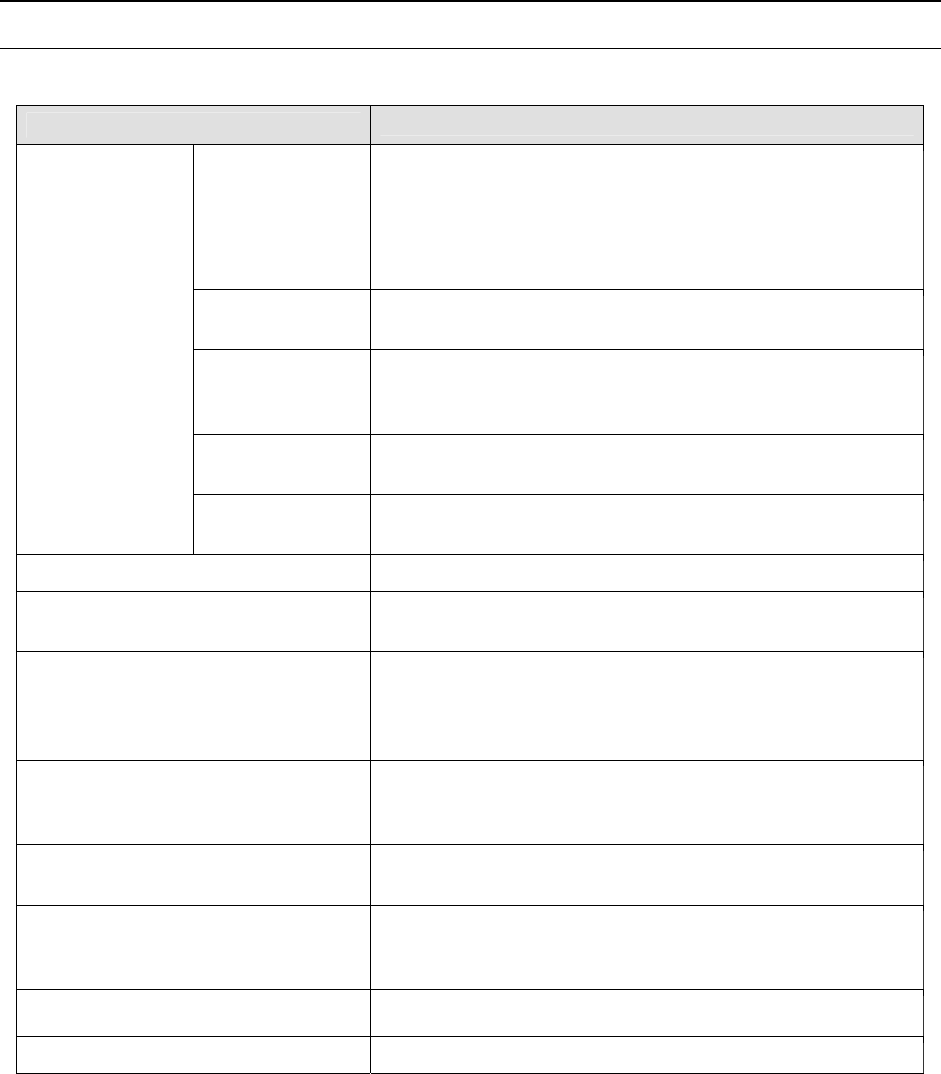
(1) Board specifications and supported languages
JX-300LED
Board
dimensions (mm)
When clamped once : 610 mm×360 mm
When clamped twice : 1,200 mm×360 mm
When clamped three times (Option) : 1,500 mm×360 mm
IN/OUT buffer (Option) :410 mm×360 mm
(See Note 1.)
Board transport
direction
Left to right or right to left
Board transport
reference
position
Front reference only
Board transport
height
900±20mm
Board transport
specifications
Number of
buffers
No buffers (See Note 1.)
Applicable component height SC(6mm)NC(12mm)
Component size
(when recognized with laser)
0603 (See Note 2.) to 33.5 mm
Speed at which a square chip LED
component is placed on a board
(according to the JUKI designated
component placement pattern)
SC(6mm) : 18,200 CPH
NC(12mm) : 17,300 CPH
Speed at which a chip component is
placed on a board
(Conforming to IPC9850)
SC(6mm) : 18,300 CPH
NC(12mm) : 17,400 CPH
Component placement accuracy
(when recognized with laser)
±50μm (±3σ)
Number of components that can be
placed
Up to 40 component types (converted to the number of
components fed with an 8-mm tape when the front bank is
used)
Supported languages English, Japanese and Chinese
EN specifications None
Note 1: The machine is not equipped with any buffer as a standard device. When you add the
IN/OUT buffer option to the machine, the machine uses three buffers.
Note 2: Required HMS device(option) When use 0603 component.
(2) Recognition devices and heads
Laser recognition : LNC60
(this allows six nozzles to place small/low-profile chips on a
board at high speed.)