JX-300LED_SPE_EN01.pdf - 第17页
- 13 - 網掛け部サポートピン設置不可範囲 4.7.3 Unavailable area for placing components on a board T op side of a board Figure Area on which no component can be placed 4.7.4 Unavailable area for setting a support pin Bottom side of a bo…
- 12 -
4.7 Applicable PWBs
4.7.1 PWBs transport direction
Rightward flow (transporting from left to right, viewed from the front side)
Leftward flow (transporting from right to left, viewed from the front side)
Note: This direction is determined at the factory.
4.7.2 PWB specifications
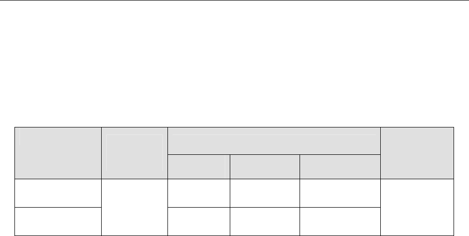
(1) PWB sizes (Unit: mm)
Maximum size(L2 x W2)
Minimum
size
(L1 x W1)
Clamped
once
Clamped
twice
Clamped three
times
Thickness
Standard
specification
610×360 1,200×360 -
Longer-sized
board (Option)
50×50
610×360 1,200×360 1,500×360
1.0 to 4.0
(actual
dimension)
Note: When “IN/OUT buffer (Option)” is used with 3 buffer operating, a borad size is able to
use up to
410×360mm.
(2) Maximum allowance of PWB mass
3,000g
(3) Allowable warpage of a PWB
0.2 mm or less per 50 mm area, and 1 mm or less for both upper and lower directions
(these values conform to the JIS B 8461 regulation.)
(4) PWB detecting sensor
A low reflectance PWB may not be detected by a sensor, independent of materials
and colors of the PWB.
- 13 -
網掛け部サポートピン設置不可範囲
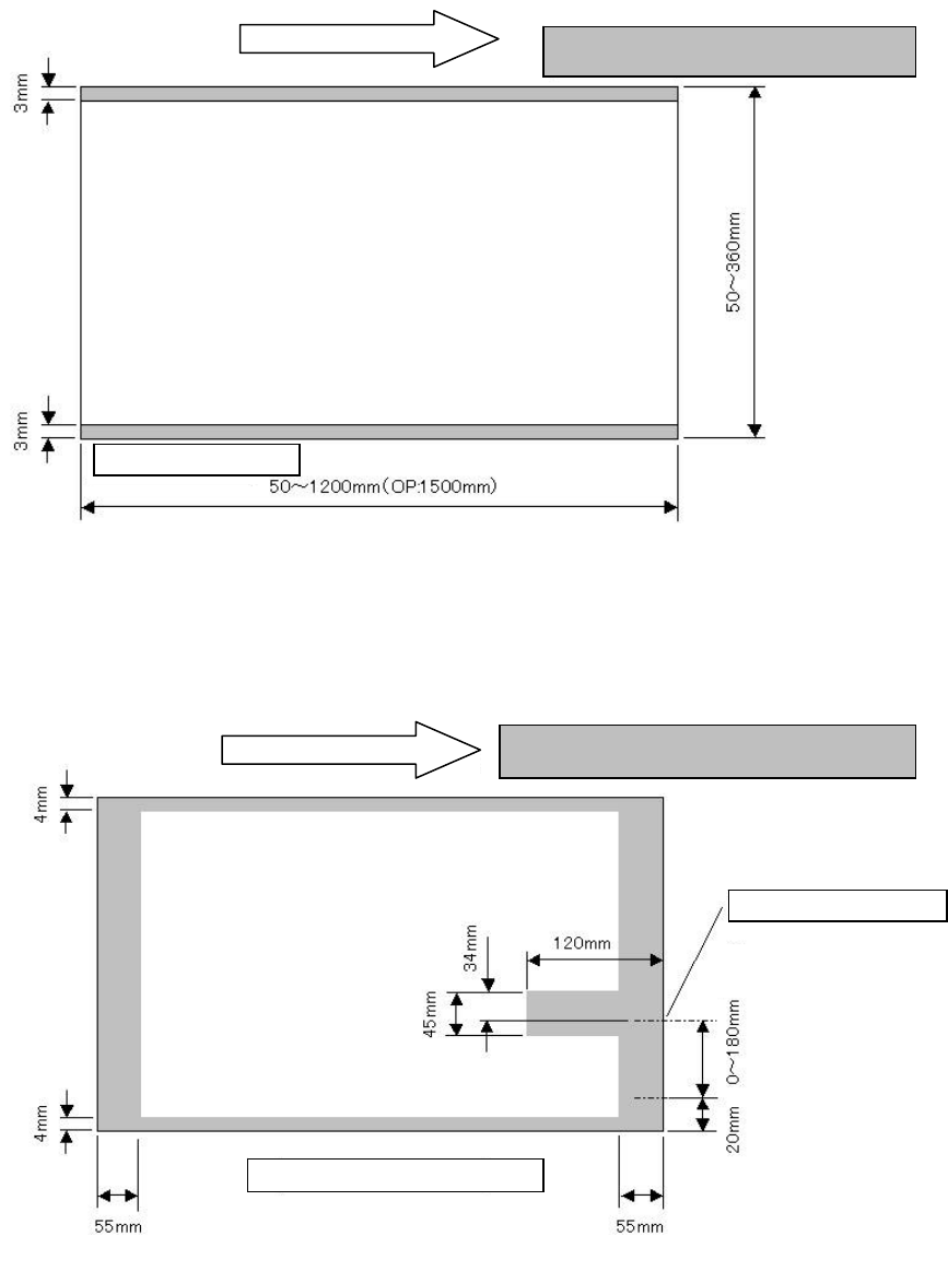
4.7.3 Unavailable area for placing components on a board
Topside of a board
Figure Area on which no component can be placed
4.7.4 Unavailable area for setting a support pin
Bottom side of a board
Note 1: When the board transport direction is opposite (from right to left), the area in which no support
pin (Option) can be set is bilaterally symmetrical to that in the figure above.
Figure Area in which no support pin can be set
Stopper setting position
Shaded area: any support pin cannot be set.
Conveyor rail fixed (reference)side
(movable)
Board trans
p
ort direction
Board trans
p
ort direction
Area in which no component can be placed
Conveyor rail fixed side
- 14 -
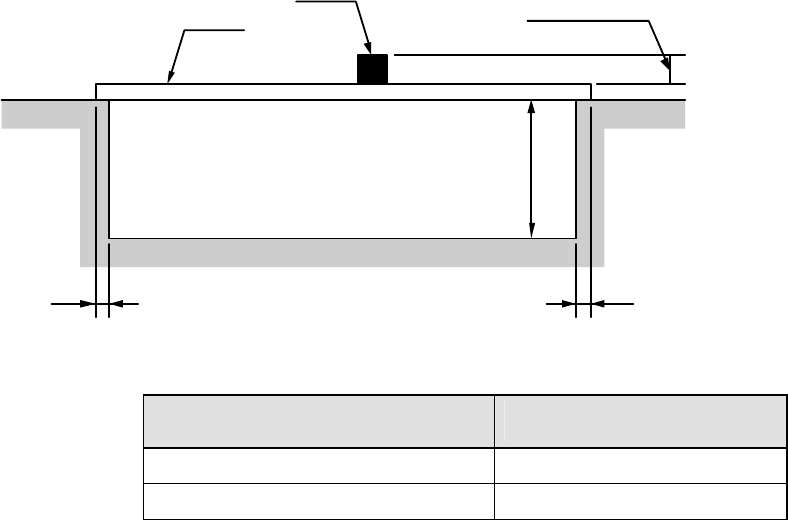
4.7.5 Area of the topside and the rear side of a board where components can be
placed
Figure Area of the topside and the rear side of a board
where components can be placed
Specification for heights of
components
H1:
component height (mm)
SC specification
6
NC specification
12
PWB transporting reference
Front reference only
PWB clamping method
This is a method for using the bottom side of a board as a reference to clamp both the
edge of the fixed side and that of the movable side with the clamp bars from above..
PWB width adjusting methods
- Standard :Manually adjusting method with your hand
- Option :Automatic PWB width adjusting method via a motor
(Minimum board size: 50.0 mm × 50.0 mm)
PWB buffer
The machine is not equipped with any buffer as a standard device. When you add the
IN/OUT buffer option to the machine, the machine uses three buffers.
See Section 5.2.10 “IN/OUT buffer” of Chapter 5 “Standard Functions and Optional
Functions” for details
PWB positioning reference
- Shape reference
Board
Component
Marginal
area on the
rear side of
the board
MAX.10mm
3 3
H1: See the table below for the dimension.