JX-300LED_SPE_EN01.pdf - 第38页
- 34 - 8.2 Specifications for Connections between the Front and Rear Devices Figure Signal interfaces and connection terminals 8.2.1 Specifications of the Connecting Cable Complied with JIS B 8438 Industrial Robot s - El…
- 33 -
8. Other Specifications
8.1 Electrical interfaces
8.1.1 Kinds and meanings of electrical signals
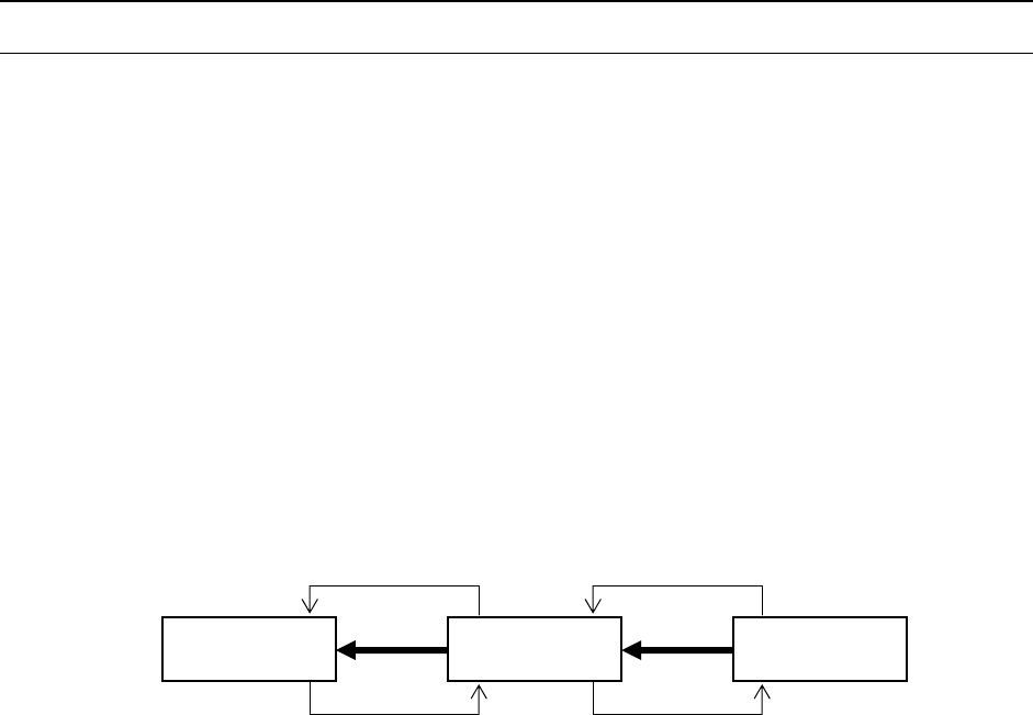
The conceptual diagram of the electrical signals both on the machines and the other side
machines is shown, as follows: The electrical signals between the machines and
upstream-side devices ①, ② and between the machines and downstream-side devices
③, ④ is shown in the following diagram.
a) The electrical signal ① is called the “carryout request input signal (or PWBs
available-in),” receiving the PWBs carryout requests from the upstream-side devices.
b) The electrical signal ② is called the “carryout permit output signal (or ready-out),”
having the PWBs carried out to the upstream-side devices.
c) The electrical signal ③ is call the “carryout request output signal (or PWBs
available-out),” requesting the PWBs carryout to the downstream-side devices.
d) The electrical signal ④ is called the “carryout permit input signal (or ready-in),
“ receiving the PWBs carryout permits from the downstream-side devices.
Figure Conceptual diagram connecting the electrical signal
Downstream-
side devices
Machine
Upstream-
side devices
④
③
②
①

- 34 -
8.2 Specifications for Connections between the Front and Rear
Devices
Figure Signal interfaces and connection terminals
8.2.1 Specifications of the Connecting Cable
Complied with JIS B 8438 Industrial Robots - Electrical Equipment
Cable length: 10m or less
8.3 Data Interface
LAN port (10/100 Base-T)
A device such as an FDD and a CD-ROM is used via USB connection.
Pin No. 1 :
Carryout permit input
signal
Pin No. 2 :
Carryout permit common
signal
Relay contact point
Downstream-
side devices
Machine
Upstream-
side devices
Pin No. 3 :
Carryout request output
signal
Pin No. 4 :
Carryout request common
signal
Pin No. 1 :
Carryout permit output
signal
Pin No. 2 :
Carryout permit common
signal
Pin No. 3 :
Carryout request input
signal
Pin No. 4 :
Carryout request common
signal
Rela
y
contact
p
oint
+24
+24V
- 35 -
9. Safety Specifications
9.1 Standards Specifications
Emergency stop
Two emergency switches on the front side and the rear side (third one also when you use
an optional HOD) bring the machine to an emergency stop: i.e. depressing these
emergency stop buttons immediately stops each axis to cut off the power supply for driving
the motors.
Safety covers
The machine is equipped with a cover on the front side. Its cover open switch detects the
open/close status of the cover, and when you open the cover, the machine stops the
continuous operation temporarily. When you start the machine even though this cover
opens, the machine is put in the low-speed operation state. When you attach an option
for the rear side operation onto the machine, the similar cover is attached on the rear side
too. When the rear cover opens in this case, the Start key and the Servo Free key of the
operation panel on the front side is disabled.
10. Reliability Specifications
10.1 Reliability of the machine (Devices)
For five (5) years: Excluding either the consumable components or the following regularly
replaceable components.
Refer to the Instruction Manual for the details of consumable components.
- Cableveyor
- Bear cable assembly
- 1394 robot cable assembly
- Optical fiber cable assembly
- Ejecter unit
- Air tube
- Filter element
- Vacuum pump
- HOD assembly
Criteria for calculating the lifetime:
22 hours per day, 300 days per year, 22 x 300 x 5 = 33,000 hours/5 years