JX-300LED_SPE_EN01.pdf - 第32页
- 28 - 6.2.5 Feeder setup stand This is platform for att aching a tape reel onto a t ape feeder . Since it allows you to att ach a tape reel on a t ape feeder while keeping the tape feeder in position, the t ape attachme…
- 27 -
6.2.4 Calibration jig for the feeder with a monitor
This Jig is for calibrating a feeder while monitoring the component pick-up position with a
CCD camera. If you check and calibrate the pick position on a regular basis, you can
maintain the stable pick-up capability.
(1) Specifications
1 Power supply Select 100 V - 120 V or 200 V - 240 V.
2 Outer dimension L=290mm, H=480mm, W=157mm
3 Mass - Adjustment jig main unit: 12 kg or less
(including the CCD camera and lens section)
- Master feeder: 2 kg
- Monitor: 4 kg
(2) Environment
① During operation
- Temperature: 10℃ to 35℃
- Accuracy guaranty temperature: 20℃ to 25℃
- Humidity: 30% to 80%RH (No condensation)
- Altitude: 1,000m or less
② Transportation and storage
- Temperature: -15℃ to 70℃
- Humidity: 20% to 95%RH (No condensation)
(3) Configuration
Standard
- Adjustment jig main unit - Master feeder
- CCD camera (including a lens) - Light
- Power supply - Monitor
- Jig tape - Adjustment tool
(4) Applicable feeders
- ATF: 8 mm to 24mm
- CTF: 8 mm
- CTFR: 8 mm
- FTF: 8 mm to 72 mm, FTFR: 32mm to 56mm
- NTF: 8 mm to 56 mm
*
Note 1
- BF: BF10AS, BF11AS, BF12BS, BF12CS, BF25CS, BF28CS and BF28RS
Note 1: One of type of 8mm and type of 12 mm to 56 mm do not have the X-direction
adjustment.
- 28 -
6.2.5 Feeder setup stand
This is platform for attaching a tape reel onto a tape feeder. Since it allows you to attach a
tape reel on a tape feeder while keeping the tape feeder in position, the tape attachment
capability is improved and it also functions to prevent a tape feeder from falling.
Two types of packages of feeder setup stand designed for a mechanical feeder are
available in response to applications.
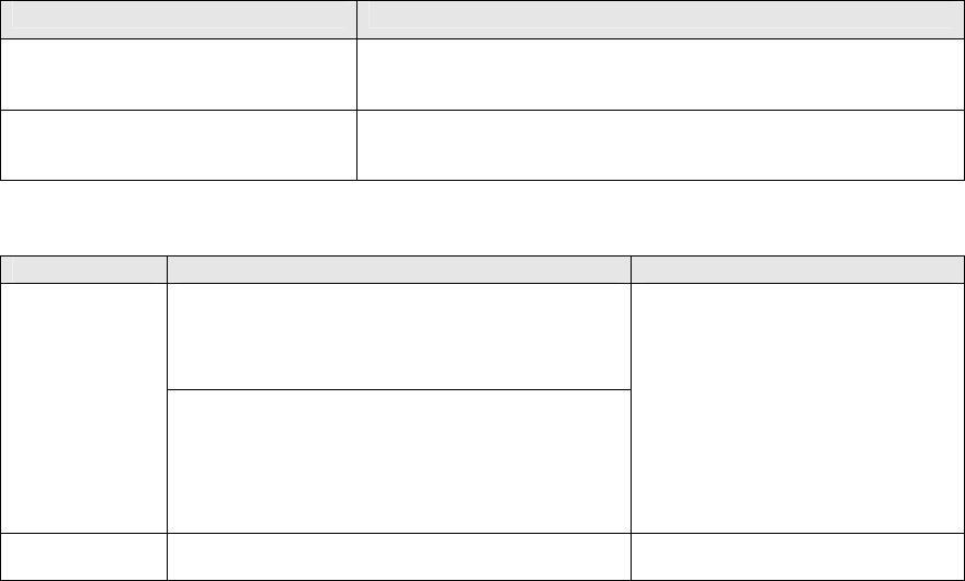
Type Application
Feeder setup stand
(With a stand)
Equipped with pedestal stand: can be installed as desired.
Feeder setup stand
(without a stand)
A user has to fix the platform on a table or similar substance with
screws.
(1) Specifications
Platform equipped with a stand Platform without a stand
- When including a feeder support section
L = 666 mm
W = 400 mm
H = 977 ± 50 mm
Outer
dimensions
- Base side only
L = 550 mm
W = 400 mm
H = 977 ± 50 mm
L = 187 mm
W = 127 mm
H = 187 mm
Mass 20 kg 1.5 kg
* The outer dimensions and mass described above indicate values to be applied when any feeder
is not mounted on the platform.

- 29 -
6.3 Stick Feeder
A stick feeder is driven by the belt without requiring any power supply or air supply.
It feeds an ordinary SOP, SOJ and PLCC that are packed in a stick.
Call the JUKI head office or local distributor for special components packed in a stick.
SOP SOJ PLCC(QFJ)
Model
Lane width
[mm]
Nominal
size
[mil]
Element
width
[mm]
Element
height
[mm]
Nominal
size
[mil]
Element
width
[mm]
Element
height
[mm]
Nominal
size
[mil]
Element
width
[mm]
Element
height
[mm]
Number of
occupied
positions
225
5.72-
6.99
-1.5
SFN0AS
(Type N0)
At delivery:
6.9
A
djustment
range:
6.6~9.2
300
7.62-
8.89
2.0
SFN1AS
(Type N1)
7.2 225
5.72-
6.99
1.5
285×
425
8.05-
8.31
SFN2AS
(Type N2)
9.2 300
7.62-
8.89
2.0 300
8.38-
8.76
290×
490
8.13-
8.51
4.20-
5.08
350
4.20-
4.57
SFN3AS
(Type N3)
11.2 375
9.35-
10.8
2.5 350
9.65-
10.03
350×
550
9.78-
10.03
4.20-
5.08
400
10.92-
11.30
450
4.20-
4.57
SFN4AS
(Type N4)
13.0 450
11.43-
12.7
3.0
450
12.19-
12.57
3.25-
3.76
450×
550
12.32-
12.57
4.20-
5.08
3
SFW1AS
(Type W1)
15.0 525
13.34-
14.61
3.5
SFW2AS
(Type W2)
18.2 600
15.24-
16.51
4.0 650
17.40-
17.65
SFW3AS
(Type W3)
20.8 750
19.94-
20.19
SFW4AS
(Type W4)
26.0
950
25.02-
25.27
SFW5AS
(Type W5)
31.2
1150
30.1-
30.55
4.20-
5.08
6
- For Types N1 to N4 and types W1 to W5, an optional spacer kit is available for a
change to another type.
- Type N0, the clearance can be finely adjusted by attached spacer to secure the lane
width for SOP 8 pins and 10 pins.