JX-300LED_SPE_EN01.pdf - 第23页
- 19 - 5.2.3 Liquid crystal touch panel This is an input device to operate the device by touching the screen. This device can be operated intuitively to improve the operability . 5.2.4 Feeder positio n indicator function…
- 18 -
5. Standard Functions And Optional Functions
5.1 Standard Functions
5.1.1 Support up to 1,200 mm as the X axis of a board
When the X dimension of a board is 610 mm or less, the machine clamps it once to
transport it. When it exceeds 610 mm but it is 1,200 mm or less, the machine clamps it
twice to transport it. In this way, the machine can produce a PWB whose size is up to
1,200 mm that is to be used in a LED light.
The whole length of the board transport path is 1,920 mm.
5.1.2 Feeder float detecting sensor (Front side only)
This function is provided to prevent mechanical troubles caused by improper installation
of tape or stick feeders. When this sensor detects an improperly-installed feeder, it
stops the X-Y axes, and warns an operator.
5.2 Optional Functions
5.2.1 Height Measurement System (HMS) (Factory-set option)
When preparing the pick data, the component pick position and height shall all be
measured via the laser sensors. Components (for example, LEDs) whose pick surface is
transparent such as glass and a substance in a mirror state from which the light is fully
reflected, blue components shall all be excluded from the subjects of the HMS. The
HMS is used to set a teaching spot also.
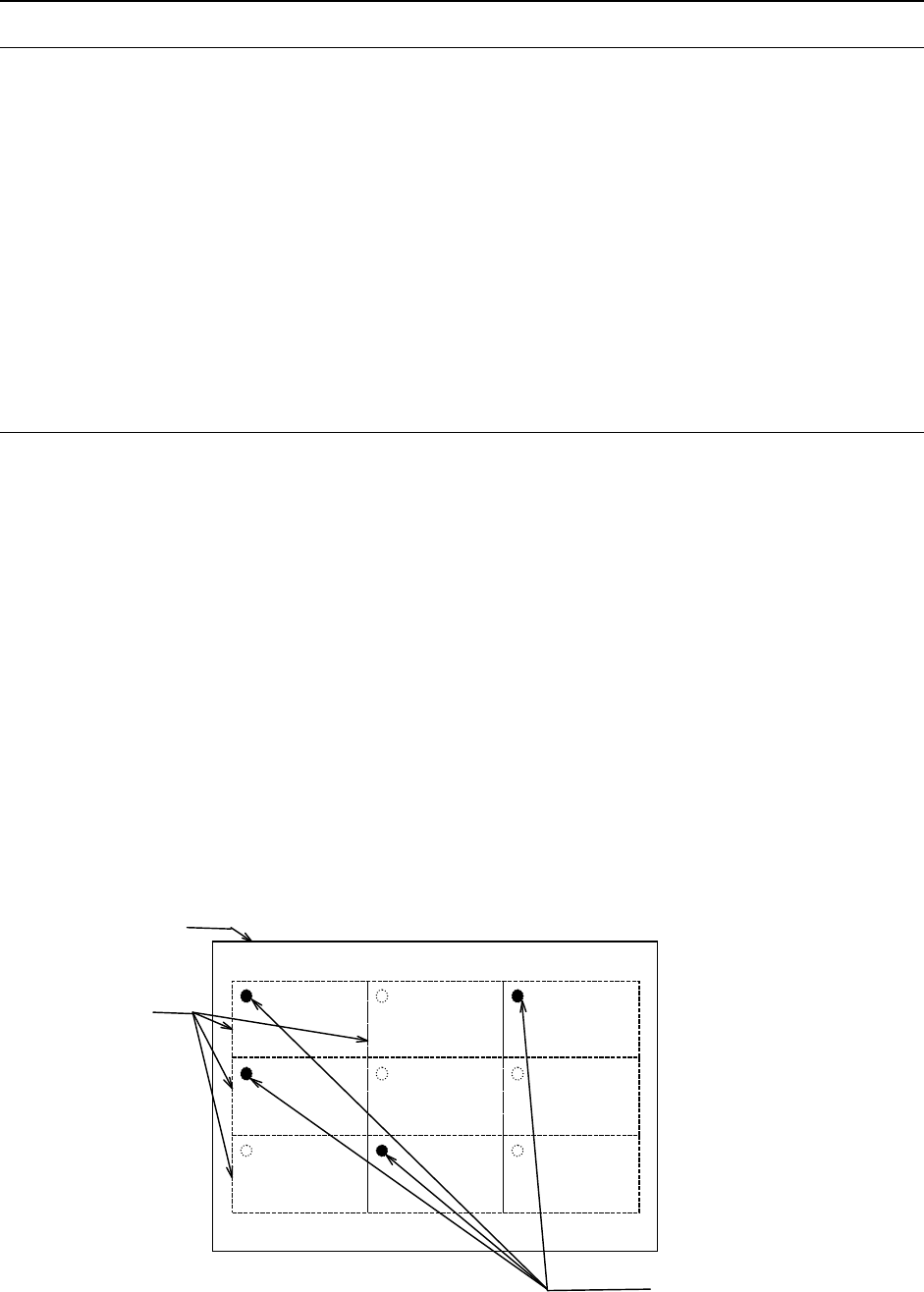
5.2.2 Bad mark reader (Factory-set option)
A bad mark is given to a circuit on a multi-circuit PWB to prevent any component from
being placed on the circuit.
The minimum diameter of a bad mark is 2.5 mm or more and the color of a mark should
be highly contrasted with the color of a board. The brightness can be switched when the
color of a board is bright (looks white).
When you use an optional bad mark reader, the time for recognizing one bad mark can
be shortened by approximately 0.1 seconds with comparing with the time taken with the
standard OCC camera.
Figure Bad marks
Circuit
Board
Bad marks
- 19 -
5.2.3 Liquid crystal touch panel
This is an input device to operate the device by touching the screen. This device can
be operated intuitively to improve the operability.
5.2.4 Feeder position indicator function
(FPI, Factory-set option) (Front side only)
This function uses LEDs to notify an operator of the feeder position to be checked if the
stocked components run out or a feeder error occurs during production of PWBs. This
feature shortens the time spent for replacing a feeder and improves the operability of the
machine.
5.2.5 Longer-sized PWB in X axis (X-dimension:1,500 mm)
(Front side only)
The PWB size in the X-axis can be extended up to 1,500 mm by clamping it three times.
As a result, the machine can produce a board whose X dimension is up to 1,500 mm to
be used in a product such as an LED light.
While the whole length of the board transport path of a standard machine is 1,920 mm,
that of the machine equipped with this option is 2,520 mm: 300 mm longer on each side,
and total 600 mm is extended.
5.2.6 Lighting unit for solder recognition (Factory-set option)
The solder print can be recognized as BOC mark when there is no BOC mark on the
PWB or the circuit.
When the longer-sized PWB is transported, the placement pad etc. on which the solder
print is performed at the placement of components in the range where the BOC mark is
not prepared can be used as BOC mark.
* Satisfactory placement accuracy might not be obtained in the solder print because the
shape as a mark is not clear.
5.2.7 Component quantity control (Option)
The lot of the product (PWB) where the components (LED components etc.) are placed is
managed.
When a PWB is loaded, it is checked whether components required to complete a
production of the PWB remain in the feeders with components in different lots not being
mixed in a PWB.
If components are not enough, a warning is displayed before the placement starts.
5.2.8 Handheld operating device (HOD: Factory-set option)
The machine allows you to check the recognized mark image on the operation screen or
perform various teaching operations. In addition, if an experienced user of any of
conventional machines does not want to change the operability of the machine, or if you
want to make the operability of the entire line consistent, you can use the HOD as
conventionally.
5.2.9 Flexible calibration system (FCS: Option)
After a jig component that is recognized with the laser is placed on a glass jig board, the
Flexible Calibration System (FCS) uses a camera to automatically measure the
difference between a value set with the program and the position at which the component
is placed, and calculates the offset value to be used for placing the component.
This series of operations are automatically performed with your setting of a board and
loading of a program into the system.
When you use the FCS, you can check whether the precision is maintained at relocation
or routine maintenance.
The system software is included as standard software, and if you purchase the jig parts
set, you can use this option for two or more machines.
- 20 -
5.2.10 IN/OUT buffer (Option)
One sensor is added to the loading side and the unloading side respectively to allow a
production program producing a large-sized board (410 mm×360 mm) to operate three
buffers. This shortens the time required to load/unload a board during PWB production.
However, a production program producing a board larger than a large-sized board
operates no buffers.
5.2.11 Support table (Factory-set Option)
When you set the required the support table for a board that may be warped, the support
table moves up to support the rear of the board and correct its warping when the board is
clamped. The support pins are included 16 pins. Place necessary number of support
pins.
5.2.12 Tray Station (Factory-set option)
This tray station is equipped with one tray, and can be installed at the corresponding
position of the rear bank so that the head of the main unit can pick up a component
directly from this station.
This tray station is fixed and its width is equivalent to that of two full-type of tray holders
(80 occupied positions on the rear bank).
When the tray size is small, several trays can be attached on the holder to allow this
holder to function as a multi-tray holder.
5.2.13 Air coupler (Piping joint) (Option)
The air coupler connecting plug for theφ8×φ12 hose
5.2.14 Software to support production (Option)
(1) EPU (External Programming Unit)
This is software for creating a production program for the machine on a personal
computer (PC) because the machine cannot allow you to create any production
program while it is producing a PWB.. The screen displayed on a PC is exactly same
as that of the machine. Even while a machine is running productions, you can edit a
production program and manage a component database on a PC with this software.
(2) Flexline CAD
With this software you can convert text data files in ASCII format and production
programs created with a CAD system for other manufacture’s machines to the JUKI
format. This enables you to shorten the time to create production programs, and to
more easily transfer production programs to the JUKI production lines from others.
* For detailed information on converting data from other manufacture’s machine,
please contact JUKI sales or the representative office in your area.