JX-300LED_SPE_EN01.pdf - 第25页
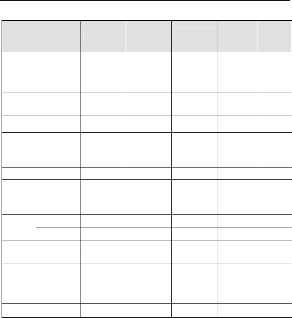
- 21 - 6. Optional Feeders 6.1 Maximum Number of Feed ers Available on the Machine Feeder name A number of available pl aces at the front side A number of available pl aces at the rear side Total number of places avail a…
- 20 -
5.2.10 IN/OUT buffer (Option)
One sensor is added to the loading side and the unloading side respectively to allow a
production program producing a large-sized board (410 mm×360 mm) to operate three
buffers. This shortens the time required to load/unload a board during PWB production.
However, a production program producing a board larger than a large-sized board
operates no buffers.
5.2.11 Support table (Factory-set Option)
When you set the required the support table for a board that may be warped, the support
table moves up to support the rear of the board and correct its warping when the board is
clamped. The support pins are included 16 pins. Place necessary number of support
pins.
5.2.12 Tray Station (Factory-set option)
This tray station is equipped with one tray, and can be installed at the corresponding
position of the rear bank so that the head of the main unit can pick up a component
directly from this station.
This tray station is fixed and its width is equivalent to that of two full-type of tray holders
(80 occupied positions on the rear bank).
When the tray size is small, several trays can be attached on the holder to allow this
holder to function as a multi-tray holder.
5.2.13 Air coupler (Piping joint) (Option)
The air coupler connecting plug for theφ8×φ12 hose
5.2.14 Software to support production (Option)
(1) EPU (External Programming Unit)
This is software for creating a production program for the machine on a personal
computer (PC) because the machine cannot allow you to create any production
program while it is producing a PWB.. The screen displayed on a PC is exactly same
as that of the machine. Even while a machine is running productions, you can edit a
production program and manage a component database on a PC with this software.
(2) Flexline CAD
With this software you can convert text data files in ASCII format and production
programs created with a CAD system for other manufacture’s machines to the JUKI
format. This enables you to shorten the time to create production programs, and to
more easily transfer production programs to the JUKI production lines from others.
* For detailed information on converting data from other manufacture’s machine,
please contact JUKI sales or the representative office in your area.
- 21 -
6. Optional Feeders
6.1 Maximum Number of Feeders Available on the Machine
Feeder name
A number of
available places
at the front side
A number of
available places
at the rear side
Total number of
places available
A number of
slots
occupied
Remarks
8 mm tape feeder
40 ― 40 2
12 mm tape feeder 26 ― 26 3
16 mm tape feeder 26
―
26 3
24 mm tape feeder 20 ― 20 4
32 mm tape feeder 16 ― 16 5
32 mm paper adhesive
tape feeder
―
―
― 5
44 mm tape feeder 10 ― 10 8
56 mm tape feeder 10 ― 10 8
72 mm tape feeder 8 ― 8 10
Stick feeder type N 26 ― 26 3
Stick feeder type W 13 ― 13 6
Stack stick feeder ― ― ― 8
Bulk feeder 40 ― 40 2
Full type ― ― -
42
Tray holder
Half type ― ― -
21
Tray station ― 1 1 80
DTS (TR1SNR) ― ― ― 48
MTS (TR5SNR)
― 1(40-stages) 1(40-stages) 80
MTS (TR5DNR) ― ― ― 80
MTC (TR6SNR) ― ― ― ―
MTC (TR6DNR)
― ― ― ―
- 22 -
6.2 Tape Feeders
6.2.1 CTFR
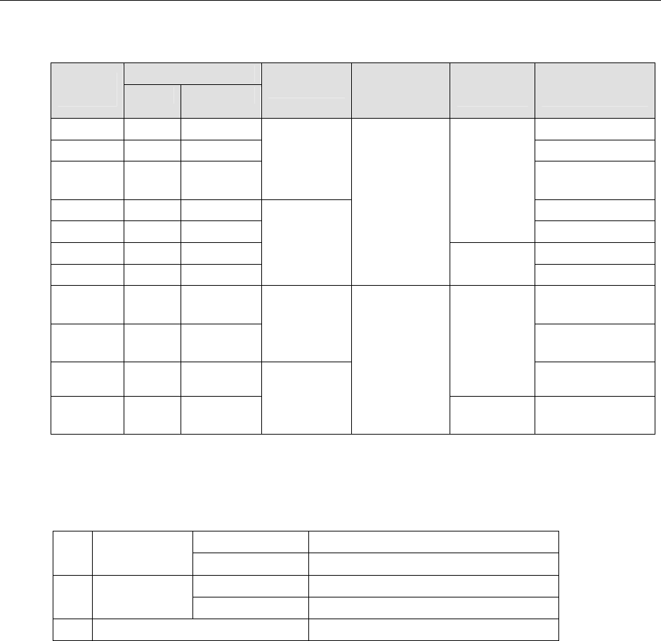
(1) Specifications
Tape type
Product
code
Paper Embossed
Feeding pitch
Number of
pins
at the edge
Diameter of
a reel
Typical component
type
CF03HPR ○ - 0603
CF05HPR ○ - 1005
CF08HER - ○
2mm
Two-terminal
diode
CF081PR ○ - 1608, 2012, 3216
CF081ER - ○
Φ180mm
SOT
CF8L1PR ○ - 1608, 2012, 3216
CF8L1ER - ○
4mm
Two
Φ180 −
Φ380mm
SOT
CN05HP
R
○ - 1005
CN08HE
R
- ○
2mm
Two-terminal
diode
CN081CR ○ ○
Φ180mm
1608, 2012, 3216
CN8L1CR ○ ○
4mm
One
Φ180 −
Φ380mm
1608, 2012, 3216
* For a tape feeder designed for both paper and embossed paper, contact our sales person.
* Use a tape feeder whose supported component sizes and tape specifications conform to the
JIS C0806-3:1999 and IEC 60286-3:2007.
(2) Common specifications
C*0***R L=602mm, H=208mm, W=16.2mm
1 Dimensions
C*8L1*R L=683mm, H=431mm, W=16.5mm
C*0***R 1.2kg (Excluding a reel)
2 Mass
C*8L1*R 1.9kg (Excluding a reel)
3 Component transport method Ratchet drive system