JX-300LED_SPE_EN01.pdf - 第37页
- 33 - 8. Other Specifications 8.1 Electrical interfaces 8.1.1 Kinds and meanings of electrical signals The conceptual diagram of the electrical signals both on the machines and the other side machines is shown, as follo…

- 32 -
7. Control System
7.1 Control
7.1.1 Saving a program
The machine stores a production program onto the SSD in the main unit.
When you use a USB port, you can store it on an external storage device also.
7.1.2 Limit of a production program
- Maximum number of placement points per circuit :3,000 points
- Maximum number of circuits per PWB :1,200 for a matrix board
200 for a non-matrix board
- Maximum number of points per PWB :10,000 points
- Maximum number of component data records :Maximum number of component
types that can be attached on the
machine
- Maximum number of component pick-up records :Same as the above.
- Maximum number of registered marks :50 sets of area marks/component
positioning marks
- Number of necessary BOC marks :When the X-aixs of a board
Up to 610 mm : 1 set (2 to 3 marks)
From 610 to 1,200 mm : 2 sets (4 to 6 marks)
From 1,200 to 1,500 mm : 3 sets (6 to 9 marks)
7.2 Production Mode
The following three production modes are available during production:
PWB production
- Specifies the number of PWBs you plan to produce and produces PWBs actually.
Trial mode
- Performs a trial PWB production.
You can select the PWB pick-up position tracking function or PWB placement position
tracking function that is to be performed after placement.
Dry run mode
- Checks the PWB pick-up/placement process without using any component.
You can select the PWB pick-up/placement position tracking function.
- 33 -
8. Other Specifications
8.1 Electrical interfaces
8.1.1 Kinds and meanings of electrical signals
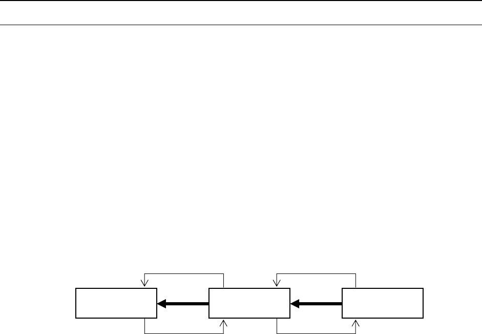
The conceptual diagram of the electrical signals both on the machines and the other side
machines is shown, as follows: The electrical signals between the machines and
upstream-side devices ①, ② and between the machines and downstream-side devices
③, ④ is shown in the following diagram.
a) The electrical signal ① is called the “carryout request input signal (or PWBs
available-in),” receiving the PWBs carryout requests from the upstream-side devices.
b) The electrical signal ② is called the “carryout permit output signal (or ready-out),”
having the PWBs carried out to the upstream-side devices.
c) The electrical signal ③ is call the “carryout request output signal (or PWBs
available-out),” requesting the PWBs carryout to the downstream-side devices.
d) The electrical signal ④ is called the “carryout permit input signal (or ready-in),
“ receiving the PWBs carryout permits from the downstream-side devices.
Figure Conceptual diagram connecting the electrical signal
Downstream-
side devices
Machine
Upstream-
side devices
④
③
②
①

- 34 -
8.2 Specifications for Connections between the Front and Rear
Devices
Figure Signal interfaces and connection terminals
8.2.1 Specifications of the Connecting Cable
Complied with JIS B 8438 Industrial Robots - Electrical Equipment
Cable length: 10m or less
8.3 Data Interface
LAN port (10/100 Base-T)
A device such as an FDD and a CD-ROM is used via USB connection.
Pin No. 1 :
Carryout permit input
signal
Pin No. 2 :
Carryout permit common
signal
Relay contact point
Downstream-
side devices
Machine
Upstream-
side devices
Pin No. 3 :
Carryout request output
signal
Pin No. 4 :
Carryout request common
signal
Pin No. 1 :
Carryout permit output
signal
Pin No. 2 :
Carryout permit common
signal
Pin No. 3 :
Carryout request input
signal
Pin No. 4 :
Carryout request common
signal
Rela
y
contact
p
oint
+24
+24V