JX-300LED_SPE_EN01.pdf - 第18页
- 14 - 4.7.5 Area of the topside and the rear si de of a board where components can be placed Figure Area of the top side and the rear side of a board where component s can be placed Specification for height s of compone…
- 13 -
網掛け部サポートピン設置不可範囲
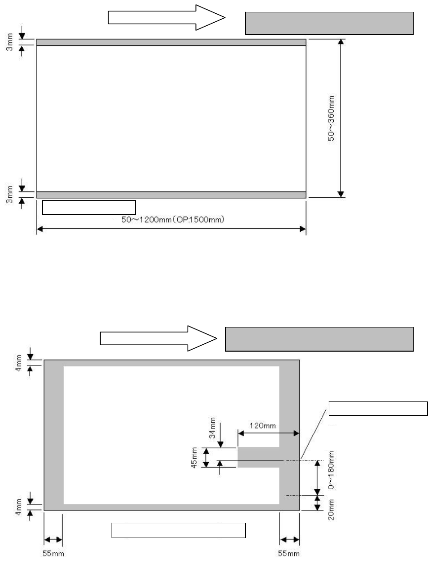
4.7.3 Unavailable area for placing components on a board
Topside of a board
Figure Area on which no component can be placed
4.7.4 Unavailable area for setting a support pin
Bottom side of a board
Note 1: When the board transport direction is opposite (from right to left), the area in which no support
pin (Option) can be set is bilaterally symmetrical to that in the figure above.
Figure Area in which no support pin can be set
Stopper setting position
Shaded area: any support pin cannot be set.
Conveyor rail fixed (reference)side
(movable)
Board trans
p
ort direction
Board trans
p
ort direction
Area in which no component can be placed
Conveyor rail fixed side
- 14 -
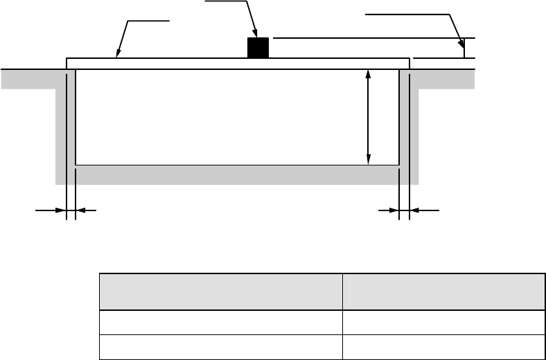
4.7.5 Area of the topside and the rear side of a board where components can be
placed
Figure Area of the topside and the rear side of a board
where components can be placed
Specification for heights of
components
H1:
component height (mm)
SC specification
6
NC specification
12
PWB transporting reference
Front reference only
PWB clamping method
This is a method for using the bottom side of a board as a reference to clamp both the
edge of the fixed side and that of the movable side with the clamp bars from above..
PWB width adjusting methods
- Standard :Manually adjusting method with your hand
- Option :Automatic PWB width adjusting method via a motor
(Minimum board size: 50.0 mm × 50.0 mm)
PWB buffer
The machine is not equipped with any buffer as a standard device. When you add the
IN/OUT buffer option to the machine, the machine uses three buffers.
See Section 5.2.10 “IN/OUT buffer” of Chapter 5 “Standard Functions and Optional
Functions” for details
PWB positioning reference
- Shape reference
Board
Component
Marginal
area on the
rear side of
the board
MAX.10mm
3 3
H1: See the table below for the dimension.
- 15 -
4.7.6 Function for correcting the PWB positions
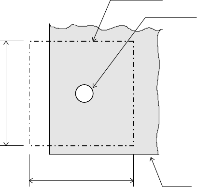
Field of vision for recognizing the PWB reference marks
6.3 mm (camera’s field of vision for recognition).
Figure Field of vision for recognizing the PWB reference marks
Window size for recognizing the PWB reference marks
This size can be changed within a maximum of 6.3 mm, subject to securing a clearance
between the recognition mark and its surrounding area.
Kinds of recognition marks and corrective method
- PWB reference mark
Two or three marks are located on a PWB to correct the entire PWB.
When the machine detects two PWB reference marks, it corrects the positioning,
angle and expansion/contraction of the entire PWB. When detecting three PWB
reference marks, it corrects the perpendicularity in the X and Y direction also.
- Component positioning marks
If a component such as an IC (QFP) needs to be placed on a board very precisely,
two or three marks set on the component itself are used to correct each component
placement position.
- Marks used to position the component area
Two marks (their positions can be set as you like) are to be provided to a group of
components placement positions, and they are used to correct each component
placement position in the group.
Note 1: You can set a mark at any position. However, if three reference marks are set, they
must not be aligned with one another. (It is recommended that these marks be set at
corners of the board.)
Note 2: When the machine supports feeding of a board whose size exceeds 610 mm
×
360 mm
twice, one set of two or three reference marks is required for each feeding operation
(total four or six marks). When it supports optional feeding of a board whose size
exceeds 1,200 mm
×
360 mm three times, one set of two or three reference marks is
required for each feeding operation (total six or nine marks).
Field of vision for PWBs recognition
Recognition mark
PWB
6.3mm
6.3mm