JX-300LED_SPE_EN01.pdf - 第6页
- 2 - ③ Simultaneous Component Pick-Up Priority mode allows you to restrict the productivity decrease caused by a simultaneous pick-up failu re to the minimum. ④ The HMS (Option) allows you to check the component pick-up…

- 1 -
1. General
The machine performance and component placement technology of the JX-300LED
machine, it is equipped with a laser align sensor (LNC60) having a series of six component
placement axes. The LED mounter is designed for mounting a chip component to be
used in a medium-sized LED package, a LED diffusing lens or a long-sized board
manufactured through the special process, and those are for lighting equipment or a
backlight of a medium-sized or large-sized LCD such as a LCD TV and a monitor of a PC.
2. Features
Performance for High Speed Placement of Components
① 18,300 CPH high-speed component placement is available thanks to the laser align
sensor (LNC60) that can recognize six nozzles simultaneously. (This figure is
achieved when the machine conforms to IPC9850, its reference side is the front, it is
designed as an SC machine (6 mm), and square chips larger than a 1005 component
are mounted on boards.)
② LED square chips can be mounted at high speed: 18,200 CPH. (This figure is
achieved when the machine reference side is the front, the machine is designed as an
SC machine (6 mm), a 12-mm tape feeder is used and sequential component
placement is performed after three nozzles are used at the same time to pick up
components twice.)
③ The twin motors drive synchronically both X and Y axis so that the high-speed control
for a shorter distance can effectively be operated.
④ The Flexible Calibration System (FCS), which allows the machine itself to recognize a
component placement position error and correct it, can maintain the component
placement accuracy that is realized at the factory or control the component placement
accuracy after the line configuration is changed. (Option)
Corresponding Longer-sized board
① The machine can handle the following dimensions of a board: 610 mm×360 mm
when clamped once, 1,200 mm×360 mm when clamped twice or 1,500 mm×360 mm
(Option) when clamped three times. <New Function>
Effective tact
① A matrix arrangement automatic tool change unit (ATC) allows nozzles for six heads to
be replaced at the same time.
② A board is positioned by being clamped twice or three times (Option) with the
mechanical stopper. <New Function>
③ Board reference marks are read for recognition in the optimized order, and the waiting
time for recognition is shortened for high-speed operation. <New Function>
Space Saving
① The machine designed for a 1,200-mm long-sized board attains the highest space
saving in the series.
② The low-profile feature improves the visibility of a production line.
Operation rate
① An MTS (TR5SNR) can be used for tray components that run out frequently.
② Dial screws can be used to adjust the board transport sensors for loading/unloading
boards. Therefore, you do not have to use any other tools.
- 2 -
③ Simultaneous Component Pick-Up Priority mode allows you to restrict the productivity
decrease caused by a simultaneous pick-up failure to the minimum.
④ The HMS (Option) allows you to check the component pick-up height and to perform a
teaching operation easily to prevent the operation rate from being lowered by a
component pick-up error.
Low Frequency of Failure Occurrence
① Since the laser unit continues monitoring the component pick-up condition until just
before a component is placed on a board, it allows you to check whether a component
drops or not.
② The function of self-calibrating the timing of releasing the vacuum pressure prevents
the components at a placement moment from being brought back.
③ Use of a vacuum pump greatly improves the stability of air supply available when the
machine picks up a component. (Option)
Versatility
① A bad mark indicating a defective circuit can be detected with an offset correction
camera (OCC).
② An LNC60 head can recognize up to 33.5 mm component with laser.
High Flexibility
① Program data created with a conventional CX or KE-series Machine can be loaded to
the machine.
② The machine performs idle board transportation even though the servomotors of the
heads or those of the X-Y axes are put in the free state.
Operability
① Displaying the graphics in rich facilitated an ease of operating the data inputs
② Key operations can be made easier by using a touch panel. (Option)
③ Provided with an option of feeder position indicator (FPI), the stocked components run
out or warns that the number of the remaining components is below the regulated
number with lighting the corresponding LED. This feature indicates which feeder is to
be replaced. (Option)
④ As a displayed language, English, Japanese and Chinese are supported depending on
the destination country.
⑤ Attachment of a USB port allows this mounter to use an external USB device. The
program can be shifted and backed up to an external recording unit.
High Serviceability
① The serviceability has been enhanced by displaying the screens of absorption
frequencies per nozzle and of X/Y axis traveling distances to call a checking time, in
addition to the hour meter (energized hours).
② Protecting the passwords has hierarchically stratified the maintenance levels to
increase a degree of freedom in setting the machine.
③ For the troubleshooting by operators, the HELP functions were fulfilled.
④ A head filter being a consumable part is installed in the upper part of the head to
facilitate replacement.
- 3 -
3. System Configuration
3.1 JX-300LED System Configuration
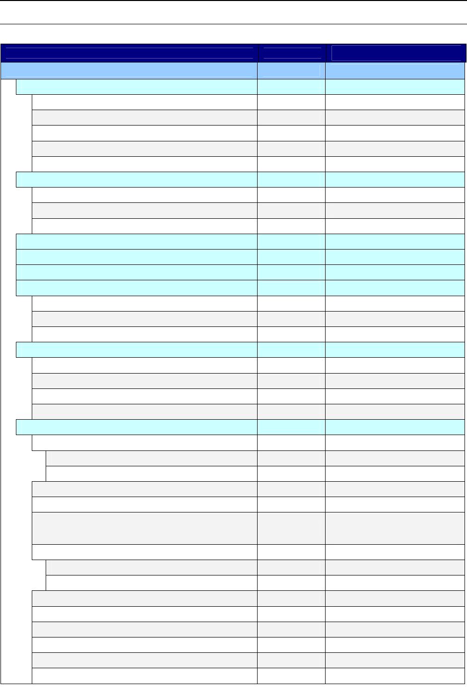
○: Equipped as standard ●: Option - : No setting
Machine style JX-300LED
Remarks
Basic configuration
Head unit
○
Laser recognition head(LNC60)
○
Offset collection camera L(OCC L)
○
Height measuring unit(HMS)
●*1
Bad mark reader(BMR)
●*1
Placement Monitor -
Power supply unit
○
Emergency stop button
○
Uninterruptible Power-supply System (UPS)
●*1
Electrical leakage breaker
●*1
I/O control unit
○
Motor control unit
○
X-Y control unit
○
Interior/exterior finish and equipment
○
Signal light (with buzzer)
○
Super foot
●*1
Caster
●*1
Pneumatic device piping system
○
Air regulator
○
Vacuum pump
●*1
Main line filter
●*1/○*2
Air coupler (Piping joint)
●*1
PWB conveyor unit
○
Board transport reference
○
Front reference
○
Rear reference -
Conveyor height 900 mm
○
Conveyor height 950 mm -
IN/OUT buffer (3 buffers)
●*1
For a board size up to 410 mm
in X axis
Placement station
○
Shape reference
○
Pin reference -
Support table unit
●*1
Including 16 support pins
Auto PWB width adjustment unit
●*1
Standard X-direction board size:
○
Up to 1,200mm in X-axis
Longer-sized board in X-axis
●*1
Up to 1,500mm in X-axis
Lighting unit of solder recognition
●*1
Component quantity control
●