THDP-TMDP_Instructions-077054003.pdf - 第17页
The remaining controls and features of the probe are located on the probe head. Probe inputs The maximum voltage that the probe inputs can accept depend on the probe model and the measurement points. For example, the THD…
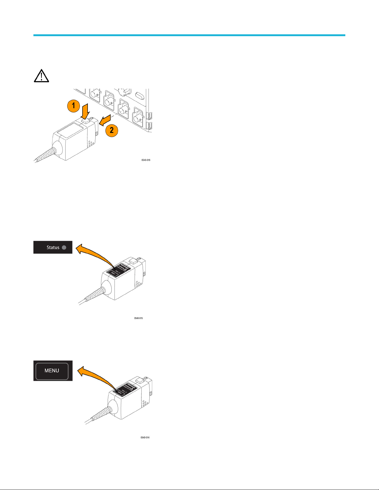
Probe release button
Press the release button to unlatch the probe from the instrument, and then pull the probe straight out.
WARNING: T
o avoid electrical shock, disconnect the probe inputs from the circuit before disconnecting the probe from the
instrument.
Status LED
When the probe is connected to the instrument, the Status LED lights amber as the probe completes a self-test. Then, the Status LED
goes of
f briefly and then lights green to indicate the probe is ready to use.
The Status LED lights amber or red if the power-on test failed, or any time an error occurs. If the Status LED light does not light green after
the self-test, first disconnect the probe from the circuit under test, and then disconnect the probe from the oscilloscope.
Reconnect the probe to the oscilloscope and check that the Status LED lights amber, and then green. If the Status LED continues to light
amber or red, there may be other remedies. See Error conditions on page 61.
Menu button
Press the MENU button to display on-screen probe controls on the oscilloscope. Many probe functions are available, such as AutoZero
and range selection.
Probe operating information
16
The remaining controls and features of the probe are located on the probe head.
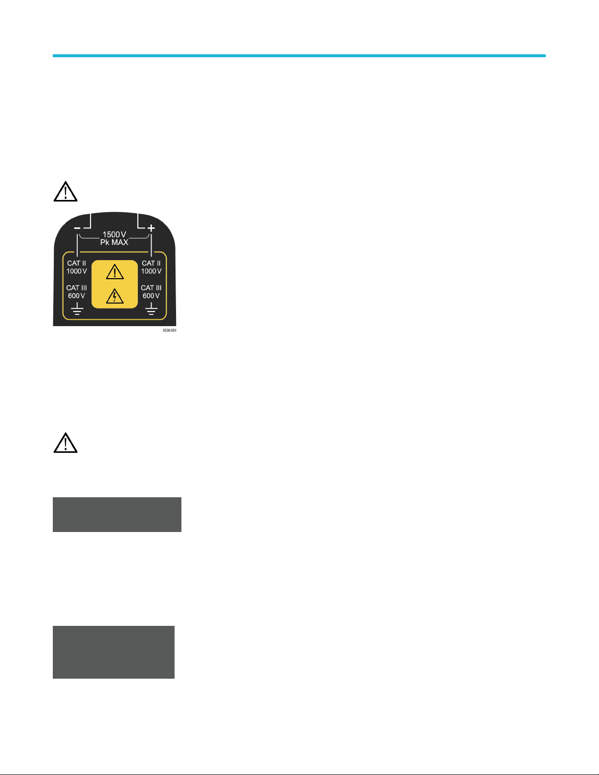
Probe inputs
The maximum voltage that the probe inputs can accept depend on the probe model and the measurement points.
For example, the THDP0200 probe (shown) can measure a maximum of 1,000 V
RMS
CA
T II between either input and ground, and a
maximum difference of 1,500 V (DC + peak AC) between the (–) and (+) inputs. These input ratings are valid for both range settings.
The other probes covered in this manual have different limits; refer to Specifications.
CAUTION: Do not use these probes above the input limits shown on the probes. The input voltage limits vary by probe model.
Overrange indicator
The OVERRANGE indicator lights red if the voltage of the input differential signal exceeds the linear range of the range setting. When this
happens, the signal on the probe output does not accurately represent the signal on the probe input.
WARNING: The Overrange indicator does not detect overrange condition of common-mode voltages or voltage-to-earth potential
at the probe inputs. The Overrange indicator only detects dif
ferentially between the + and – inputs (not relative to ground).
Do not exceed the common-mode voltage or input voltage-to-earth ratings of the probe when taking measurements. See
Overrange detection on page 37.
If you are not sure, make a single-ended measurement of each point you are intending to measure differentially first. Make a
single-ended measurement by tying one input lead to ground (the "–" input) and then connecting the other lead (the “+" input) to
the points of interest, one at a time.
Voltage range button and indicators
Press the RANGE button to select between the voltage range (attenuation) settings of the probe. The voltage range is indicated by two
LEDs on the probe and may be displayed on the oscilloscope screen, depending on the oscilloscope model.
The OVERRANGE LED lights if the applied voltage exceeds the selected range. T
o extinguish the LED, select a higher range. If a higher
range is not available, do not attempt to take the measurement with the probe.
Probe operating information
High Voltage Differential Probes THDP0100/0200 and TMDP0200 User Manual 17
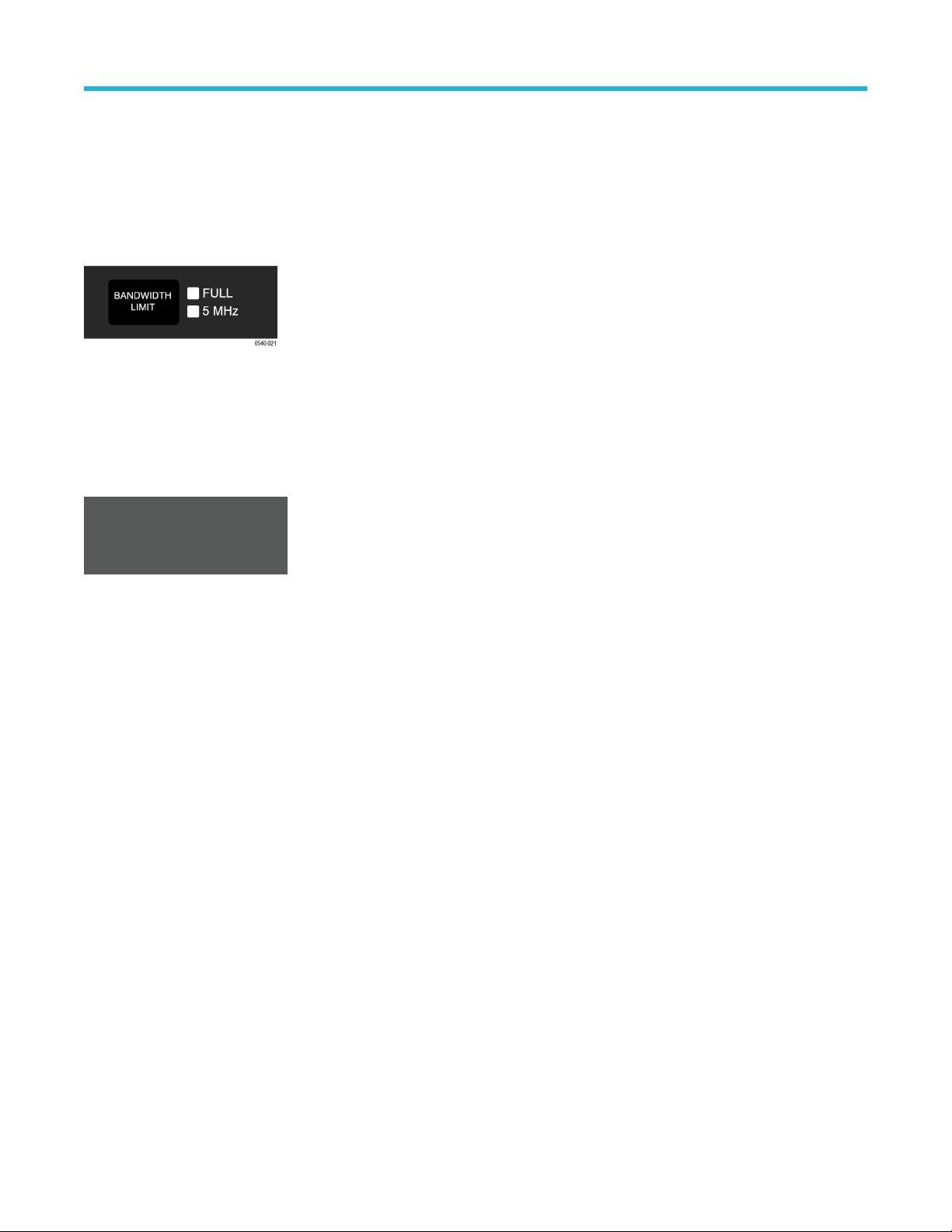
Bandwidth limit button and indicators
Press the BANDWIDTH LIMIT button to limit the probe bandwidth to 5 MHz. 5 MHz is close to the switching frequency of most switching
transistors (FET
s) in switch mode power supplies (SMPS).
The 5 MHz filter assists in the characterization and testing of power supplies in switch mode by removing all high frequency content, noise
and harmonics from the measurement.
Press the button again to return to the FULL position, which selects the full specified bandwidth of the probe.
Audible overrange on/off button and indicators
The audible overrange is an audible alarm that indicates when the measured signal exceeds the selected range. The alarm is enabled
when the probe is first powered on.
Press the AUDIBLE OVERRANGE button to light the OFF LED and disable the feature. T
o enable the alarm, press the button again to light
the ON LED.
Probe operating information
18