THDP-TMDP_Instructions-077054003.pdf - 第56页
Gain accuracy The equipment settings for this test dif fer between probes. Refer to the table for specific settings for the probe that you are testing. See T able 15 on page 56. W ARNING: Dangerous voltages will be prese…
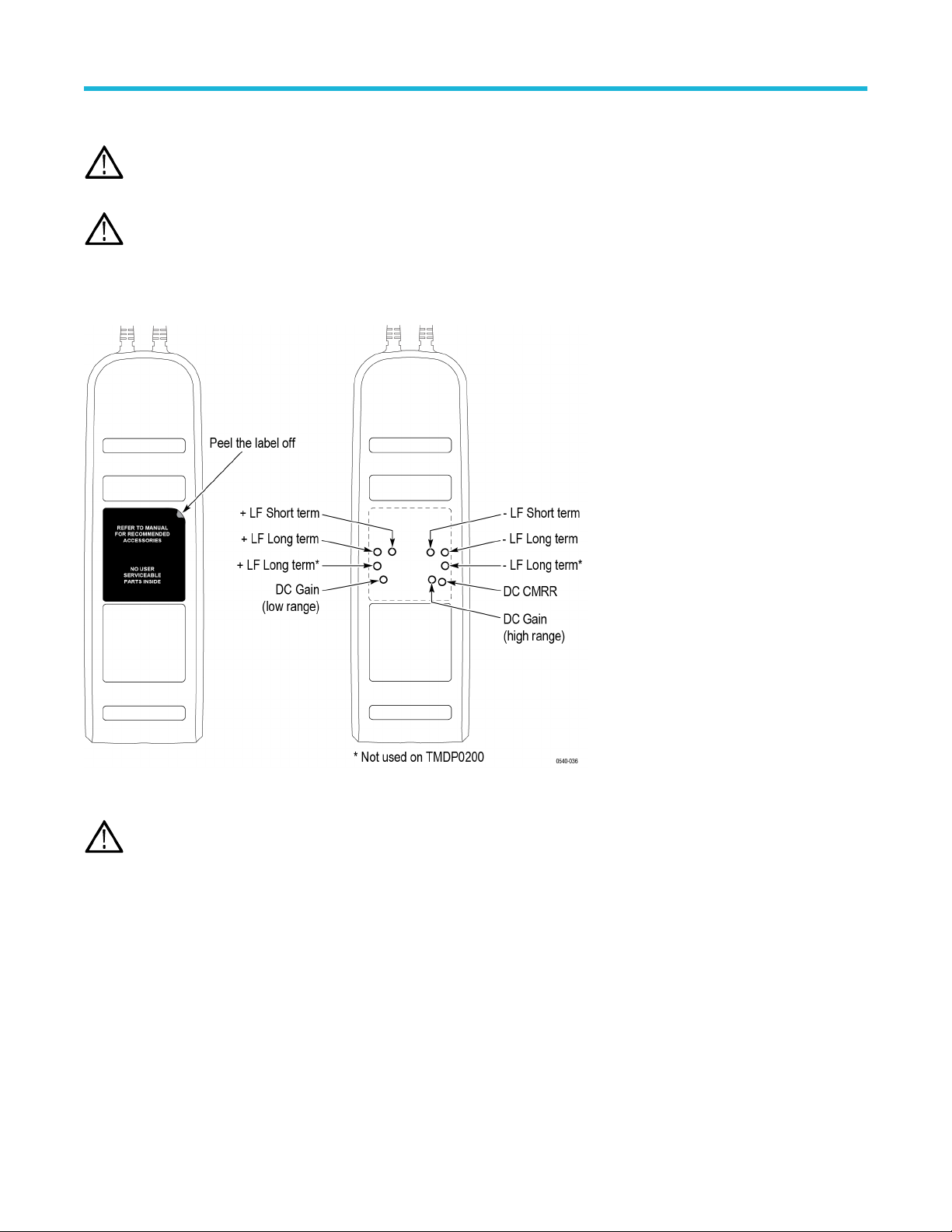
Accessing the internal adjustments
Note: Only probes with serial numbers C020000 and above have internal adjustments. Probes with serial numbers C019999 and
below that require adjustments (other than of
fset zero) must be returned to Tektronix for service.
WARNING: The remaining adjustments for the probe require you to remove a reusable label from the back of the probe. Y
ou must
replace the label after you complete the probe adjustments. Failure to do so may subject the user to high voltages present in the
probe during measurements. If you need a replacement label, refer to the Equipment Required table for the Tektronix part number.
See Table 14 on page 52.
Remove the reusable back-panel label shown below to gain access to the adjustments. Store the label in a safe place to preserve the
adhesive backing for reuse.
Figure 17: Internal adjustment locations (S/N C020000 and above only)
CAUTION: Y
ou must replace the reusable label after you complete the adjustment procedures. Failure to do so may subject
the user to high voltages present in the probe during measurements. If you need a replacement label, refer to the Equipment
Required table for the Tektronix replacement part number.
Adjustments
High Voltage Differential Probes THDP0100/0200 and TMDP0200 User Manual 55
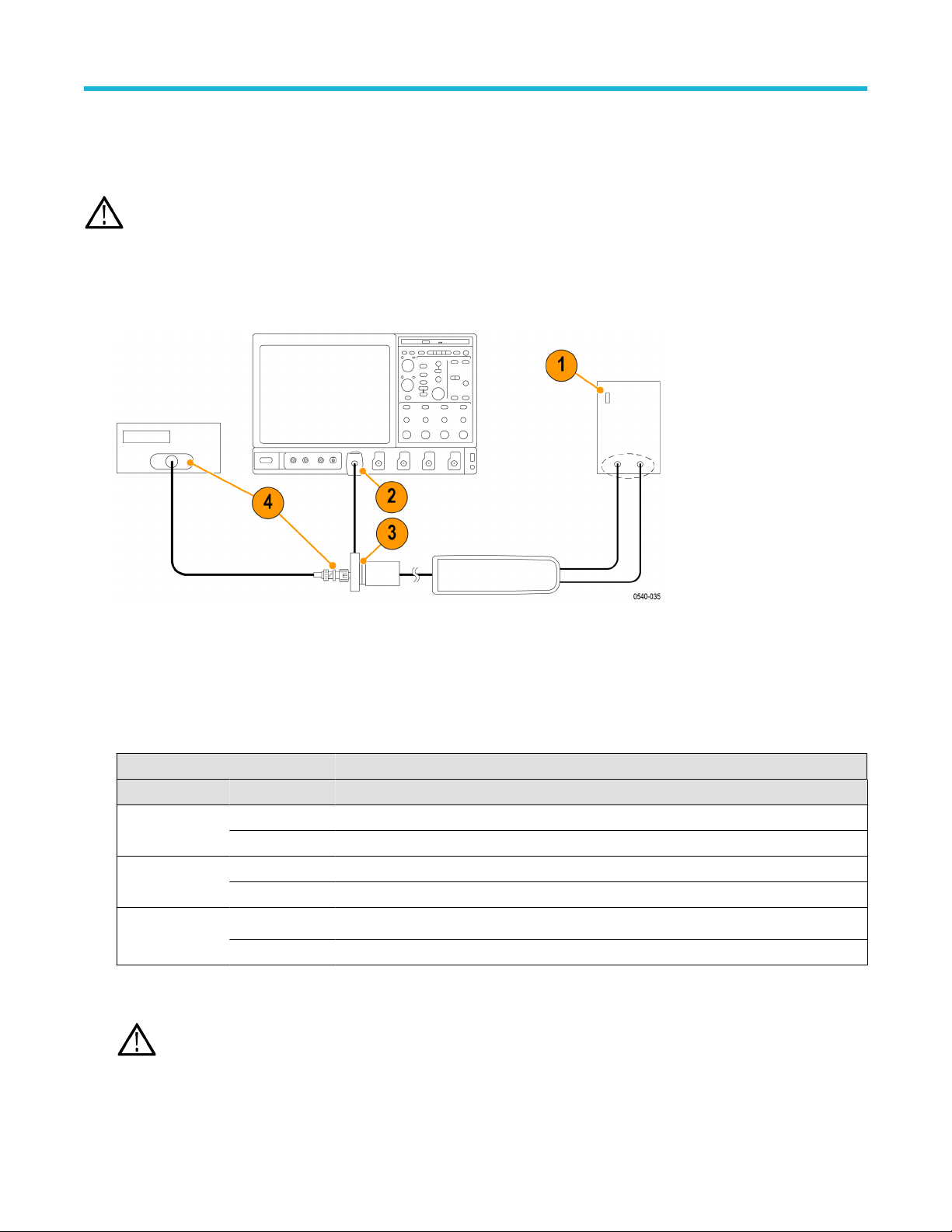
Gain accuracy
The equipment settings for this test dif
fer between probes. Refer to the table for specific settings for the probe that you are testing. See
Table 15 on page 56.
WARNING: Dangerous voltages will be present on the calibration generator output terminals and connection cables. Always verify
that the generator is in the standby mode before you make any connections to the generator
.
1. V
erify that the generator output is off.
2. Connect the probe calibration fixture to any channel (1–4) on the oscilloscope.
3. Connect the probe output to the probe calibration fixture.
4. Connect the output of the probe calibration fixture to the inputs of the DMM, using coax cables and adapters.
5. Set the DMM to AC volts.
6. Connect the probe inputs to the front outputs of the generator
, using adapters if necessary.
7. Set the probe attenuation to the lower (most sensitive) range for the probe that you are adjusting.
8. Set the generator square wave output frequency and RMS voltage (main display) to the values shown in the table for the probe that
you are adjusting. See Table 15 on page 56.
Table 15: Adjust gain accuracy equipment settings
Probe Generator square wave output Probe output voltage
Model Range Voltage (rms) Frequency Expected (rms) Measured (rms)
THDP0100 600 V 75 V 100 Hz 750 mV ±15 mV
6000 V 75 V 100 Hz 75 mV ±1.5 mV
THDP0200 150 V 25 V 100 Hz 500 mV ±10 mV
1500 V 75 V 100 Hz 150 mV ±3 mV
TMDP0200 75 V 20 V 100 Hz 800 mV ±16 mV
750 V 60 V 100 Hz 240 mV ±4.8 mV
9. Enable the generator output.
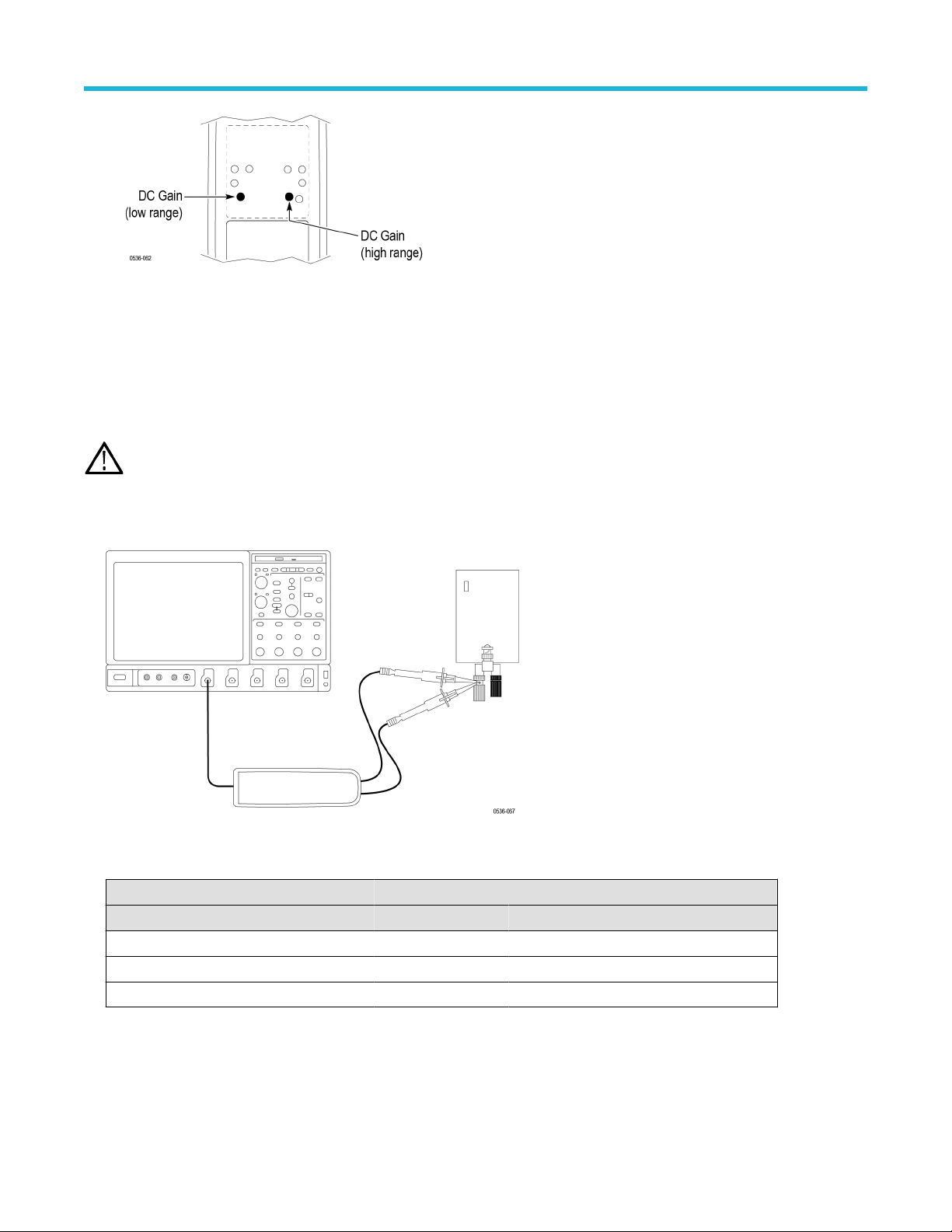
10. Adjust the low-range DC gain pot in the probe to
≤2% of the expected output.
WARNING: Use only an insulated tool to make the adjustment. Failure to do so presents a potential shock hazard.
Adjustments
56
11. Disable the generator output.
12. Set the probe attenuation to the next range and set the generator output voltage to the value shown in the table.
13. Enable the generator output and adjust the high-range DC gain pot in the probe to
≤2% of the expected output.
14. Disable the generator output.
DC CMRR
WARNING: Dangerous voltages will be present on the calibration generator output terminals and connection cables. Always verify
that the generator is in the standby mode before you make any connections to the generator
.
1. V
erify that the generator output is off.
2. Connect both of the probe inputs to the red (+) banana connector on the front output terminals of the generator. Use a BNC-banana
adapter if necessary.
3. Set the output of the generator to the voltage and frequency listed in the table.
Table 16: DC CMRR test equipment settings
Probe Generator output
Model Range Voltage (rms) Voltage (p-p) Frequency
THDP0100 600 V 353.53 V 1000 V 40 Hz
THDP0200 150 V 200 V 566 V 40 Hz
TMDP0200 75 V 353.53 V 1000 V 40 Hz
4. Set the oscilloscope horizontal to 10 ms/div and bandwidth to 5 MHz.
5. Set the probe attenuation to the lower (most sensitive) range of the probe.
6. Enable the generator output. Set the oscilloscope vertical to display the signal. For a stable display, connect the generator Sense
output to another channel and trigger off of that channel.
Adjustments
High Voltage Differential Probes THDP0100/0200 and TMDP0200 User Manual 57