THDP-TMDP_Instructions-077054003.pdf - 第54页
Offset zero This is the only procedure that applies to all of the probes and all serial numbers. Adjustment notes • For probes with serial numbers C199999 and below , Of fset Zero is the only adjustment that can be done …
Adjustment procedures
WARNING: These procedures require the application of high voltage to the inputs of the probes. Only qualified personnel
should perform any testing with voltage levels exceeding 30 V
rms
. All pertinent safety rules and guidelines for elevated voltage
measurements should be followed and adhered to.
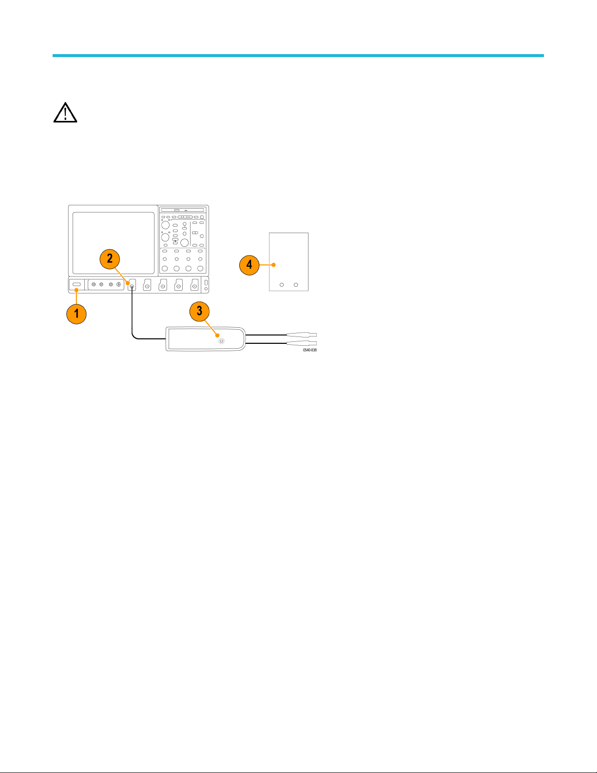
Test setup
1. T
urn on the oscilloscope.
2. Connect the probe to any channel of the oscilloscope.
3. Verify that the LEDs light on the probe.
4. T
urn on the remaining test equipment and let the probe and equipment warm up for 20 minutes.
Adjustments
High Voltage Differential Probes THDP0100/0200 and TMDP0200 User Manual 53

Offset zero
This is the only procedure that applies to all of the probes and all serial numbers.
Adjustment notes
•
For probes with serial numbers C199999 and below, Offset Zero is the only adjustment that can be done to the probe.
• For probes with serial numbers C020000 and above, Offset Zero is the only adjustment that can be done without removing the back
label.
• The adjustment for each range is independent and does not interact between the ranges.
Procedure
1. Set the oscilloscope offset to 0 volts.
2. Connect the probe inputs together with the hook tips.
3. Press and hold the probe BANDWIDTH LIMIT and RANGE buttons until the OVERRANGE LED on the probe flashes.
4. Release the buttons. The OVERRANGE LED continues to flash, indicating that the digitally-controlled of
fset zero adjustment is
enabled.
5. Use the probe BANDWIDTH LIMIT and RANGE buttons to set the probe offset voltage as close to 0 V as possible, as displayed on the
oscilloscope. The BANDWIDTH LIMIT button decreases the offset voltage and the RANGE button increases it.
6. Press the AUDIBLE OVERRANGE button on the probe to store the adjusted offset value. The OVERRANGE LED stops flashing to
indicate that the offset value is stored and that the adjustment is disabled.
7. Select the remaining attenuation range and repeat steps 3 on page 54 through 6 on page 54.
Adjustments
54
Accessing the internal adjustments
Note: Only probes with serial numbers C020000 and above have internal adjustments. Probes with serial numbers C019999 and
below that require adjustments (other than of
fset zero) must be returned to Tektronix for service.
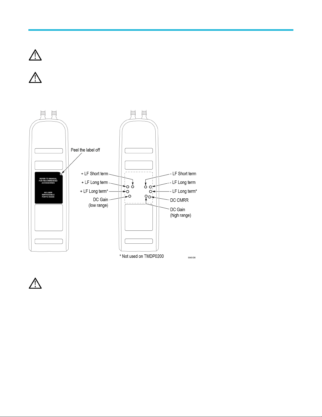
WARNING: The remaining adjustments for the probe require you to remove a reusable label from the back of the probe. Y
ou must
replace the label after you complete the probe adjustments. Failure to do so may subject the user to high voltages present in the
probe during measurements. If you need a replacement label, refer to the Equipment Required table for the Tektronix part number.
See Table 14 on page 52.
Remove the reusable back-panel label shown below to gain access to the adjustments. Store the label in a safe place to preserve the
adhesive backing for reuse.
Figure 17: Internal adjustment locations (S/N C020000 and above only)
CAUTION: Y
ou must replace the reusable label after you complete the adjustment procedures. Failure to do so may subject
the user to high voltages present in the probe during measurements. If you need a replacement label, refer to the Equipment
Required table for the Tektronix replacement part number.
Adjustments
High Voltage Differential Probes THDP0100/0200 and TMDP0200 User Manual 55